Detection method and system for leakage current of heat exchanger

A technology of heat exchanger leakage and detection method, applied in fluid tightness test, machine/structural component test, instrument and other directions, can solve problems such as production danger, affecting product quality, energy loss, etc.

Inactive Publication Date: 2014-04-30
CHINA UNIV OF PETROLEUM (BEIJING) +1
View PDF4 Cites 2 Cited by
  • Summary
  • Abstract
  • Description
  • Claims
  • Application Information

AI Technical Summary

Problems solved by technology

However, due to factors such as corrosion, inconsistent thermal expansion and contraction of various parts of the heat exchanger at high temperatures, and fluid-induced vibration, the heat exchanger is often damaged and leakage occurs from time to time, that is, the tube-side fluid flows into the shell side or the shell-side fluid. Flowing into the tube side, causing pollution and other losses between the heat-exchanging media
This kind of heat exchanger leakage phenomenon occurs in the shell, which cannot be found by naked eyes, and has great concealment.
[0003] At present, by installing flowmeters at the inlet and outlet of each heat exchanger to monitor the inlet and outlet flows of cold and hot fluids in real time, it is possible to judge whether leakage occurs. However, since petrochemical equipment includes dozens or even hundreds of heat exchangers, Installing flowmeters at the inlet and outlet of each heat exchanger will increase equipment investment costs, and in view of constraints such as space distribution and pipe fitting requirements, it is difficult to install flowmeters in pipe sections between heat exchangers for engineering implem

Method used


Image

  • Detection method and system for leakage current of heat exchanger
  • Detection method and system for leakage current of heat exchanger
  • Detection method and system for leakage current of heat exchanger

Examples


Embodiment Construction

[0056] The following will clearly and completely describe the technical solutions in the embodiments of the present invention with reference to the accompanying drawings in the embodiments of the present invention. Obviously, the described embodiments are only some, not all, embodiments of the present invention. Based on the embodiments of the present invention, all other embodiments obtained by persons of ordinary skill in the art without creative efforts fall within the protection scope of the present invention.

[0057] Embodiments of the present invention provide a method and system for detecting leakage of a heat exchanger. The present invention will be described in detail below in conjunction with the accompanying drawings.

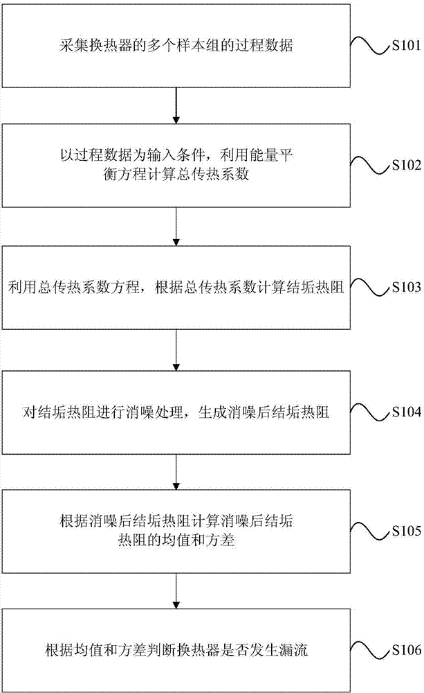
[0058] An embodiment of the present invention provides a method for detecting leakage of a heat exchanger, such as figure 1 As shown, the detection method includes the following steps:

[0059] Step 101: collecting process data of multiple sample ...


PUM


Abstract

The invention provides a detection method and system for leakage current of a heat exchanger. The detection method comprises the steps of collecting process data of a plurality of sample sets of the heat exchanger, calculating a total heat transfer coefficient through an energy-balance equation with the process data as an input condition, calculating scaling heat resistance through a total heat transfer coefficient equation according to the total heat transfer coefficient, carrying out noise elimination processing on the scaling heat resistance, generating scaling heat resistance after noise elimination, calculating the mean value and variance of the scaling heat resistance after noise elimination according to the scaling heat resistance after noise elimination, and judging whether the heat exchanger leaks or not according to the mean value and the variance. Compared with the prior heat exchange leakage current diagnostic technology, the detection method is high in calculation real-time performance and short in time delay, and is not affected by operation conditions of other devices except for the heat exchanger; the wavelet transform theory is adopted to process field data on line, influence on diagnosis results from noise is weakened, calculation accuracy is improved, implementation is facilitated, and the total cost is low.

Description

technical field [0001] The invention relates to the system engineering field of petrochemical industry, in particular to a detection method and system for heat exchanger leakage. Background technique [0002] Heat exchangers are widely used in energy recovery systems in the petrochemical process industry, which can greatly reduce their investment and operating costs. However, due to factors such as corrosion, inconsistent thermal expansion and contraction of various parts of the heat exchanger at high temperatures, and fluid-induced vibration, the heat exchanger is often damaged and leakage occurs from time to time, that is, the tube-side fluid flows into the shell side or the shell-side fluid. It flows into the tube side, causing losses such as pollution between the heat-exchanging media. This leakage phenomenon of the heat exchanger occurs in the casing, which cannot be found by naked eyes, and has great concealment. [0003] At present, by installing flowmeters at the i...

Claims


Application Information

Patent Timeline
IPC IPC(8): G01M3/00
CPCY02P20/10
Inventor 罗雄麟曲德伟杜殿林孙琳
Owner CHINA UNIV OF PETROLEUM (BEIJING)
Why Eureka
Try Eureka