Electronic gun heat measurement system for electron beam analyzer and monitoring and correction method thereof

An electron gun and analyzer technology, applied in the field of vacuum electronics, can solve the problems of manpower, material resources, incompatibility, time-consuming, etc., and achieve the effect of saving time, strong intuitiveness, and ensuring reality

Inactive Publication Date: 2014-04-30
INST OF ELECTRONICS CHINESE ACAD OF SCI
View PDF3 Cites 4 Cited by
  • Summary
  • Abstract
  • Description
  • Claims
  • Application Information

AI Technical Summary

Problems solved by technology

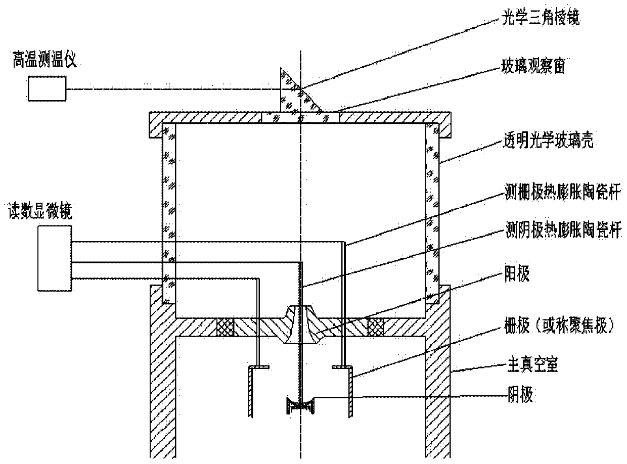
[0010] (1) Due to the interference of the ceramic rod on the measurement optical path, it is incompatible in the temperature measurement and thermal expansion experiment. The slender ceramic rod in the vacuum system needs to be replaced, the system needs to be cooled, and the vacuum chamber should be opened and then vacuumed again and reheated. The cathode temperature is measured again, and the experiment has to be repeated many times to obtain the average inter-electrode distance change, so it takes a long time, a lot of manpower and material resources, and it is difficult to accurately grasp the thermal expansion in the real thermal measurement work
[0011] (2) The electron beam analyzer cannot directly detect the distance between the grid and the anode and the distance between the grid and the cathode of the electron gun under test due to thermal expansion. Only a glass cover and a ceramic rod structure can be attached The analyzer's experiments were simulated to find
A large experiment such as the optimization of the electron gun electrode spacing structure experiment lasts for 5 to 6 hours, and each group of experiments also lasts for 1 to 2 hours. The structural deviation of the distance has greatly exceeded the allowable range, and the experimental accuracy cannot be guaranteed
Therefore, it is difficult to guarantee the requirements of the experiment by using the existing technology.

Method used


Image

  • Electronic gun heat measurement system for electron beam analyzer and monitoring and correction method thereof
  • Electronic gun heat measurement system for electron beam analyzer and monitoring and correction method thereof
  • Electronic gun heat measurement system for electron beam analyzer and monitoring and correction method thereof

Examples


Embodiment Construction

[0046] In order to make the object, technical solution and advantages of the present invention clearer, the present invention will be described in further detail below in conjunction with specific embodiments and with reference to the accompanying drawings. It should be noted that, in the drawings or descriptions of the specification, similar or identical parts all use the same figure numbers. Implementations not shown or described in the accompanying drawings are forms known to those of ordinary skill in the art. Additionally, while illustrations of parameters including particular values ​​may be provided herein, it should be understood that the parameters need not be exactly equal to the corresponding values, but rather may approximate the corresponding values ​​within acceptable error margins or design constraints. The directional terms mentioned in the embodiments, such as "upper", "lower", "front", "rear", "left", "right", etc., are only referring to the directions of the...


PUM


Abstract

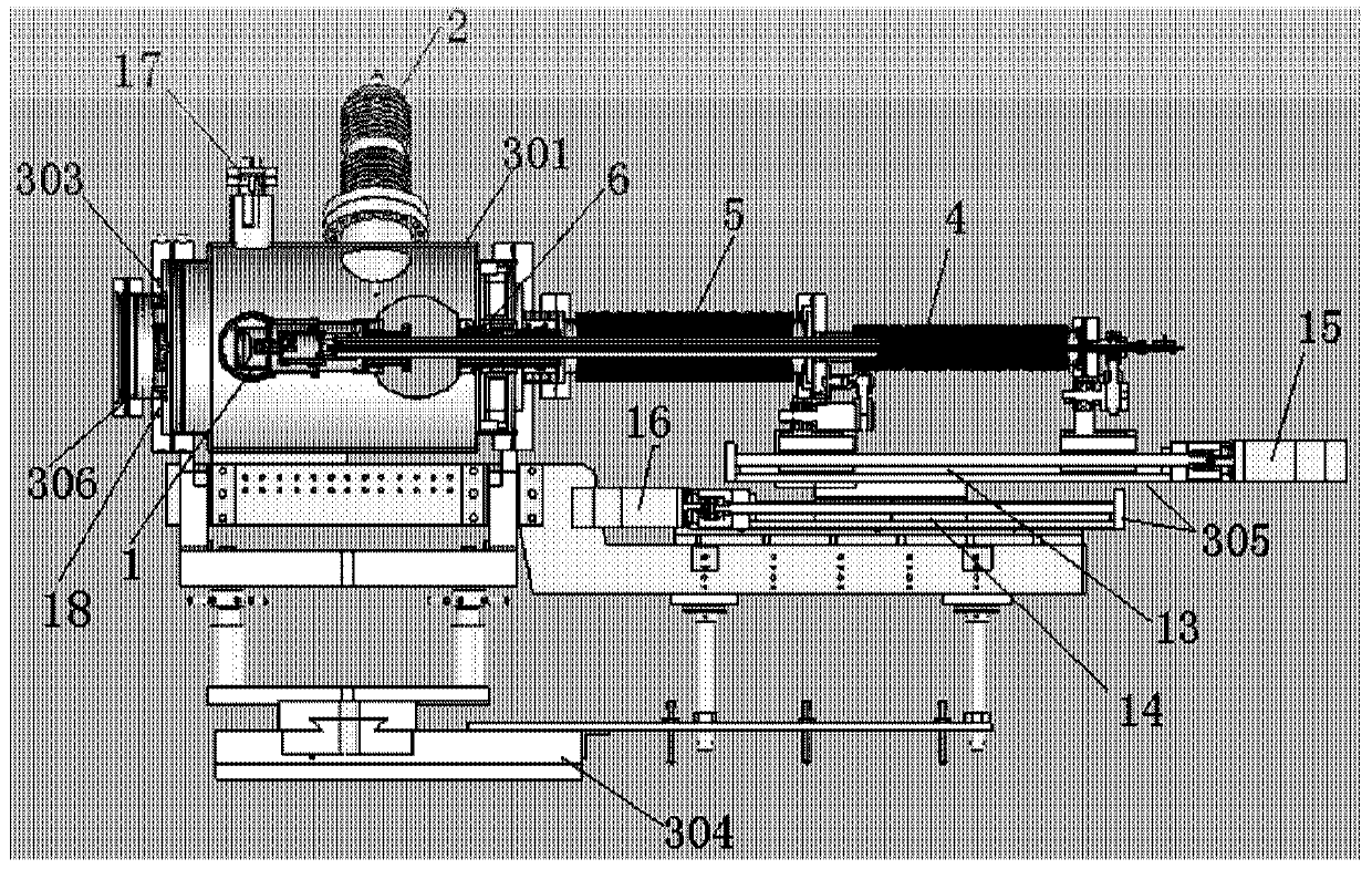
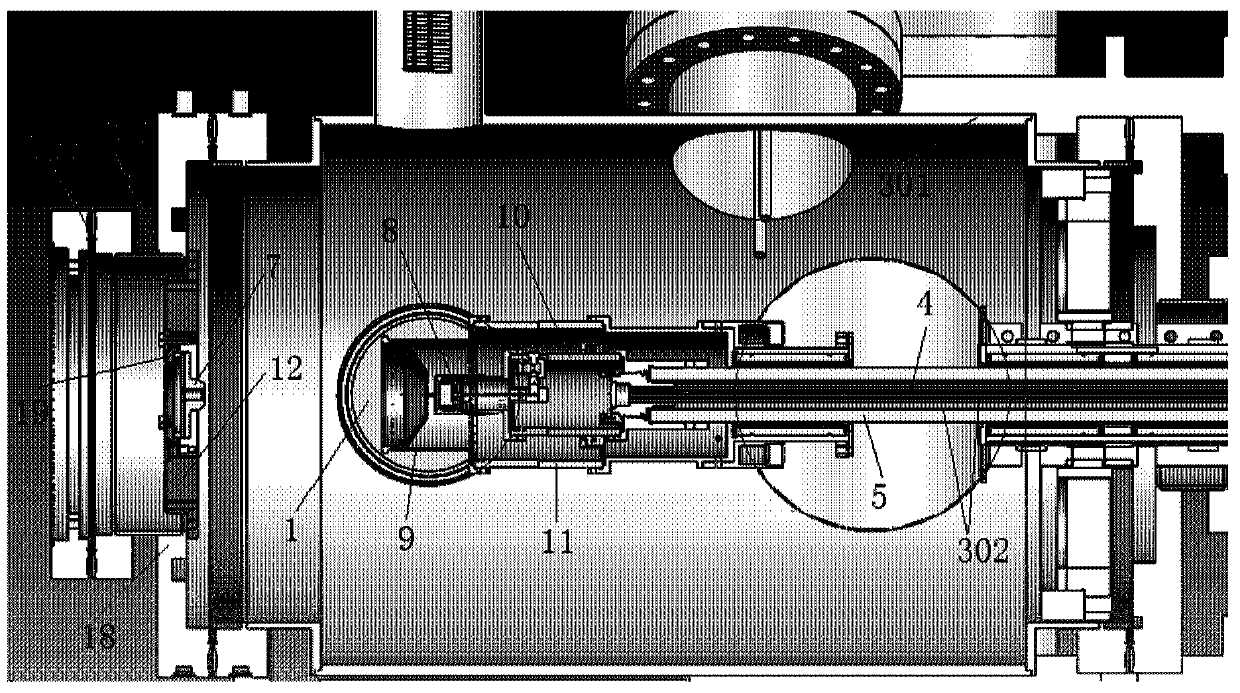
The invention provides an electronic gun heat measurement system for an electron beam analyzer and a monitoring and correction method of the electronic gun heat measurement system. The electronic gun heat measurement system comprises a main vacuum cavity, an electronic gun, a concentric shaft assembly, an optical monitoring system and a zero-touch circuit. The electronic gun is located in the main vacuum cavity and comprises an anode, a grid and a cathode, wherein the anode, the grid and the cathode are sequentially arranged in the axial direction of the vacuum cavity, the anode is fixed to the front end of the main vacuum cavity, and the grid is annular. One end of the concentric shaft assembly is inserted into the main vacuum cavity, and the other end of the concentric shaft assembly extends out of the main vacuum cavity. The concentric shaft assembly comprises a cathode inner concentric shaft and a grid outer concentric shaft, wherein the cathode inner concentric shaft is sleeved with the grid outer concentric shaft. The optical monitoring system is used for monitoring the position of the cathode and the position of the grid through a transparent observation window formed in the main vacuum cavity and a narrow and long through hole in the side face of a grid support cylinder. The zero-touch circuit is connected with the anode and the grid through feed heads arranged on the main vacuum cavity respectively and used for correcting the relative positions of the anode and the grid. The electronic gun heat measurement system for the electron beam analyzer and the monitoring and correction method of the electronic gun heat measurement system can reduce the workload of heat measurement work of the electronic gun and improve the measurement accuracy.

Description

technical field [0001] The invention relates to the field of vacuum electronics, in particular to an electron gun thermal measurement system for an electron beam analyzer and a monitoring and correction method thereof. Background technique [0002] The electron optics dynamic thermal measurement system is a system for measuring the electron optics performance of the electron gun after the cathode, grid, anode structure and mutual axial distance of the electron gun have been determined. But because the temperature of the cathode is heated to the working temperature, the supporting structure of each electrode of the electron gun is subject to different degrees of thermal expansion, which changes the distance between the cathode, the grid, and the anode. Therefore, it is necessary to measure the variation of the distance between the electrodes at the cathode working temperature before installing the thermal measurement rack, and correct it when installing the rack. Otherwise, ...

Claims


Application Information

Patent Timeline
Patent Type & Authority Applications(China)
IPC IPC(8): G01R31/00G01B11/14
Inventor 阮存军李庆生李崇山龙志翘吴迅雷李彦峰
Owner INST OF ELECTRONICS CHINESE ACAD OF SCI
Why Eureka
Try Eureka