Alarm information storing method and device

A technology of alarm information and storage space, applied in the direction of comprehensive factory control, comprehensive factory control, electrical program control, etc., can solve the problems of unavailable alarm information, alarm information loss, alarm information storage, etc., to avoid alarm information loss, comprehensive recorded effect

Active Publication Date: 2014-04-30
BEIJING NAURA MICROELECTRONICS EQUIP CO LTD
View PDF16 Cites 10 Cited by
  • Summary
  • Abstract
  • Description
  • Claims
  • Application Information

AI Technical Summary

Problems solved by technology

Due to the difference in the working cycle of the upper and lower computers, when the alarm information is maintained for less than 200ms, although the PLC can read the alarm information and make corresponding processing, and at the same time give an alarm prompt to the upper computer, it will not respond to the alarm. The information is saved, and because the working cycle of the host computer has not yet arrived, the alarm information cannot be obtained, and the user cannot know the cause of the corresponding processing results in the PLC due to the alarm, which makes it difficult to troubleshoot problems, and some alarm information. lost

Method used


Image

  • Alarm information storing method and device
  • Alarm information storing method and device
  • Alarm information storing method and device

Examples


no. 1 Embodiment

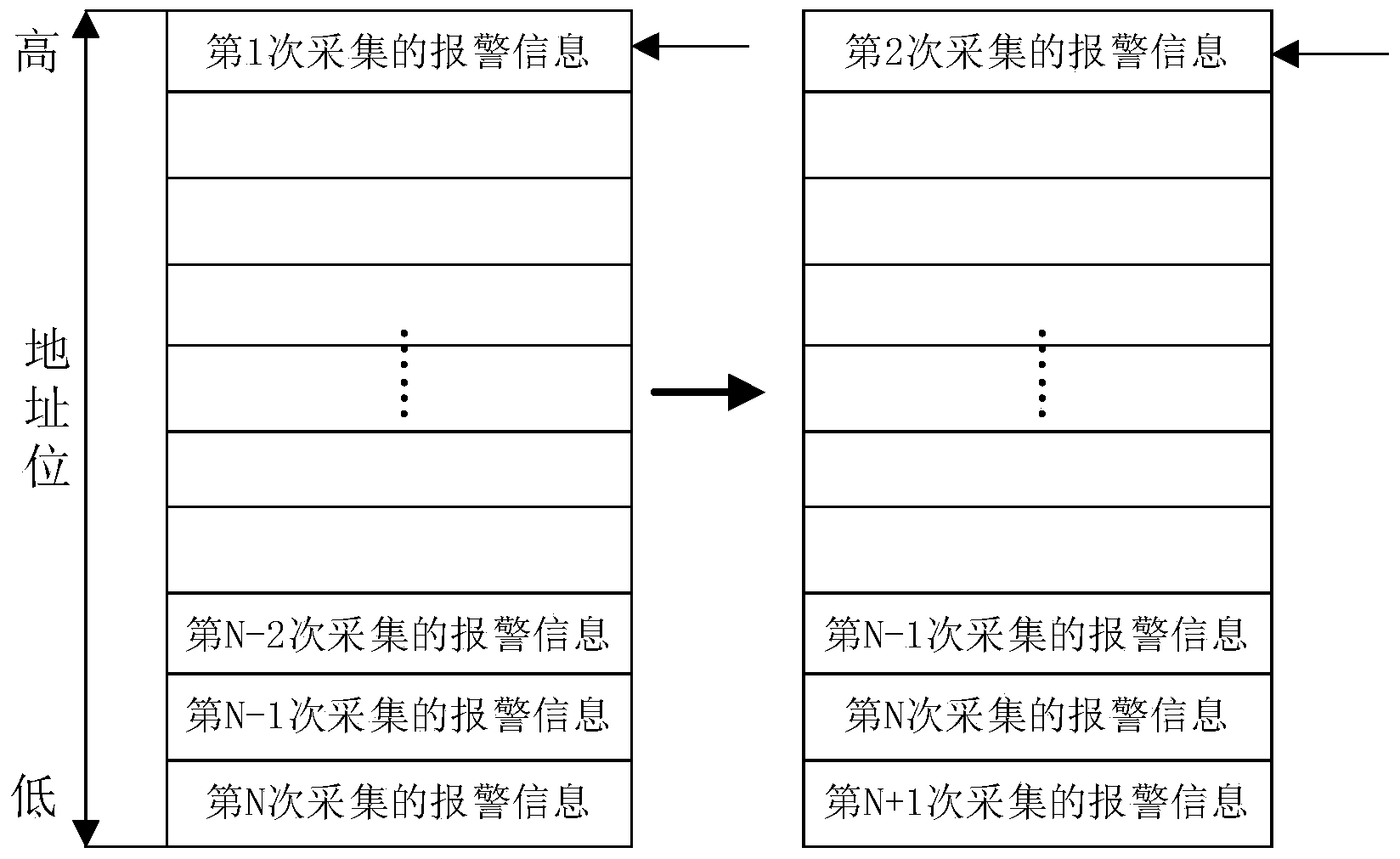
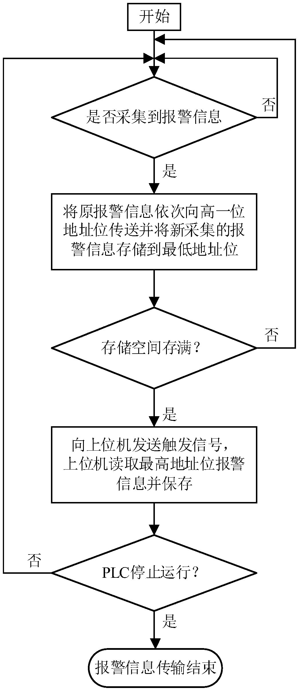
[0033] figure 2 Shown is a schematic diagram of the storage space 12a of the alarm information transmission system in this embodiment, image 3 Shown is a flow chart of the method for transmitting alarm information in this embodiment.

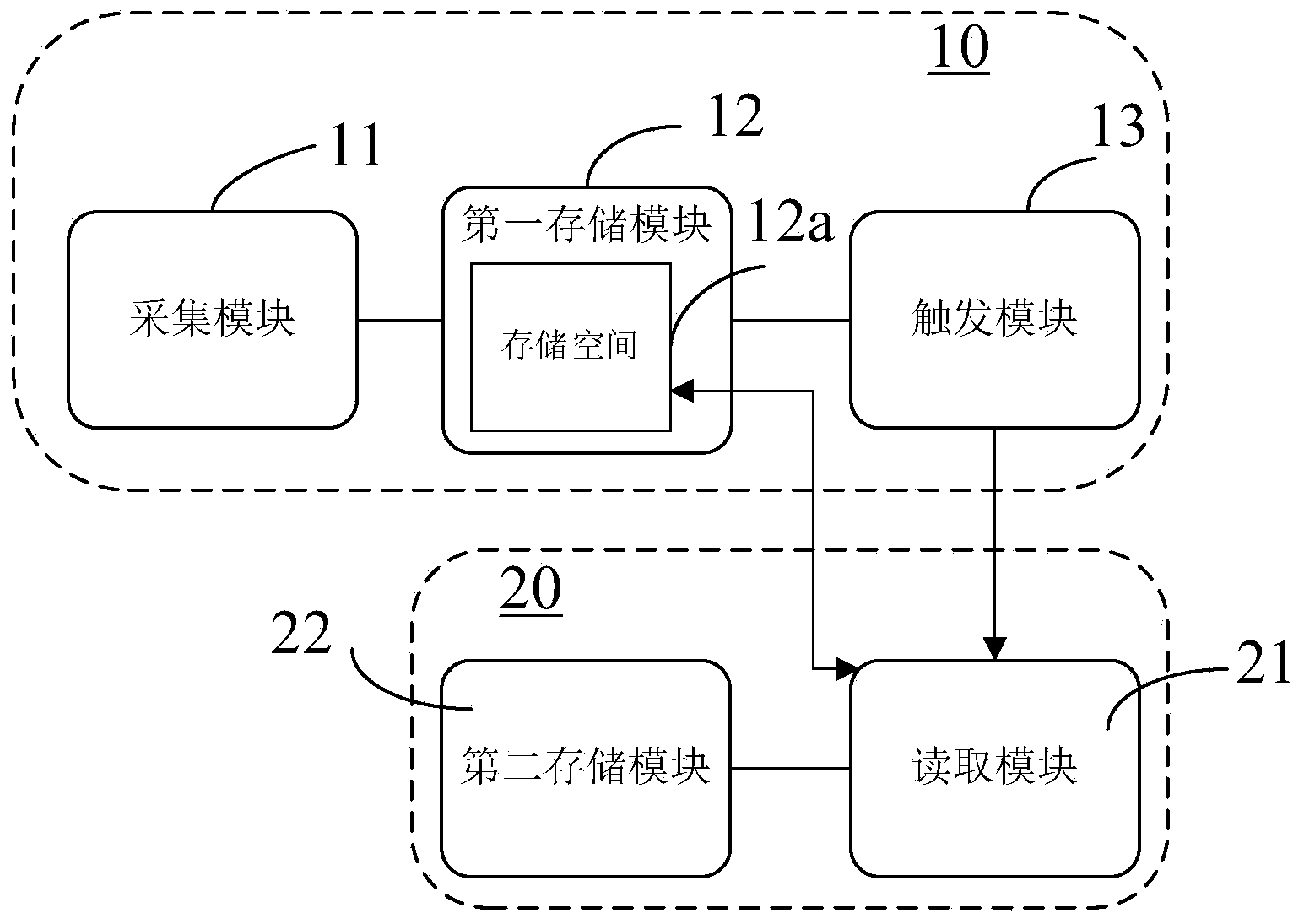
[0034] Please refer to Figure 1 to Figure 3The collection module 11 periodically reads the information of the alarm detection element to collect the alarm information. Once the alarm information is collected, the first storage module 12 stores it into the storage space 12a. After receiving the trigger signal, the reading module 21 reads the alarm information with the earliest alarm generation time in the storage space 12a. In this embodiment, the reading module 21 reads one piece of alarm information each time as an example for illustration. The first storage module 12 stores each alarm information into the storage space 12a according to the sequence of alarm generation time. Specifically, the alarm information of the early alarm generati...

no. 2 Embodiment

[0037] Figure 4 Shown is a schematic diagram of the storage space 12a of the alarm information transmission system in this embodiment, Figure 5 Shown is a flow chart of the method for transmitting alarm information in this embodiment.

[0038] The collection module 11 periodically reads the information of the alarm detection element to collect the alarm information. Once the alarm information is collected, the first storage module 12 stores it into the storage space 12a. After receiving the trigger signal, the reading module 21 reads the alarm information with the earliest alarm generation time in the storage space 12a. In this embodiment, the reading module 21 reads one piece of alarm information each time as an example for illustration. Please refer to figure 1 , Figure 4 with Figure 5 , in this embodiment, the first storage module 12 does not store the alarm information in the storage space 12a in a specific order, but preferentially stores the blank address bits w...


PUM


Abstract

The invention discloses an alarm information transmitting system which comprises a lower computer storage unit and an upper computer reading unit. The lower computer storage unit comprises a collecting module for regularly collecting alarm information, a first storage module which comprises storage space for storing the collected alarm information, a triggering module which outputs a triggering signal when the storage space is full. The upper computer reading unit comprises a reading module which is triggered by the triggering signal to read at least one piece of the alarm information in the storage space and a second storage module which is used for storing the read alarm information. The invention further provides an alarm information transmitting method. The alarm information can be comprehensively recorded and prevented from being lost by means of the alarm information transmitting system and the alarm information transmitting method.

Description

technical field [0001] The invention relates to the technical field of semiconductor process equipment control, in particular to a storage method and a storage device for alarm information. Background technique [0002] At present, the control system of domestic equipment generally adopts the control mode of upper computer + lower computer, in which the upper computer is an industrial computer, which is responsible for controlling the operation of the entire equipment, including process menu editing, scheduling and control of the functions of each control part, and monitoring of abnormal states in the process. Alarm reminder and storage of alarm information, etc. The lower computer is PLC (Programmable Logic Controller), which is connected to each part of the equipment, collects on-site signals and transmits them to the upper computer and executes the command request sent by the upper computer to control the action execution of each component. [0003] At present, the stora...

Claims


Application Information

Patent Timeline
Patent Type & Authority Applications(China)
IPC IPC(8): G05B19/418
CPCY02P90/02
Inventor 慕晓航张海轮王艾
Owner BEIJING NAURA MICROELECTRONICS EQUIP CO LTD
Why Eureka
Try Eureka