High-speed milling cutter designing method for suppressing unevenness in forced vibration wear of cutter teeth

A technology of forced vibration and design methods, applied in computing, manufacturing tools, special data processing applications, etc.

Active Publication Date: 2014-04-30
HARBIN UNIV OF SCI & TECH
View PDF3 Cites 22 Cited by
  • Summary
  • Abstract
  • Description
  • Claims
  • Application Information

AI Technical Summary

Problems solved by technology

[0008] The invention aims at solving the problem of face milling cutter tooth wear and face milling overall wear non-uniformity, and provides a high-speed milling cutter design method for suppressing the non-uniformity of forced vibration and wear of cutter teeth

Method used


Image

  • High-speed milling cutter designing method for suppressing unevenness in forced vibration wear of cutter teeth
  • High-speed milling cutter designing method for suppressing unevenness in forced vibration wear of cutter teeth
  • High-speed milling cutter designing method for suppressing unevenness in forced vibration wear of cutter teeth

Examples


Embodiment Construction

[0097] Preferred embodiments of the present invention will be described in detail below with reference to the accompanying drawings.

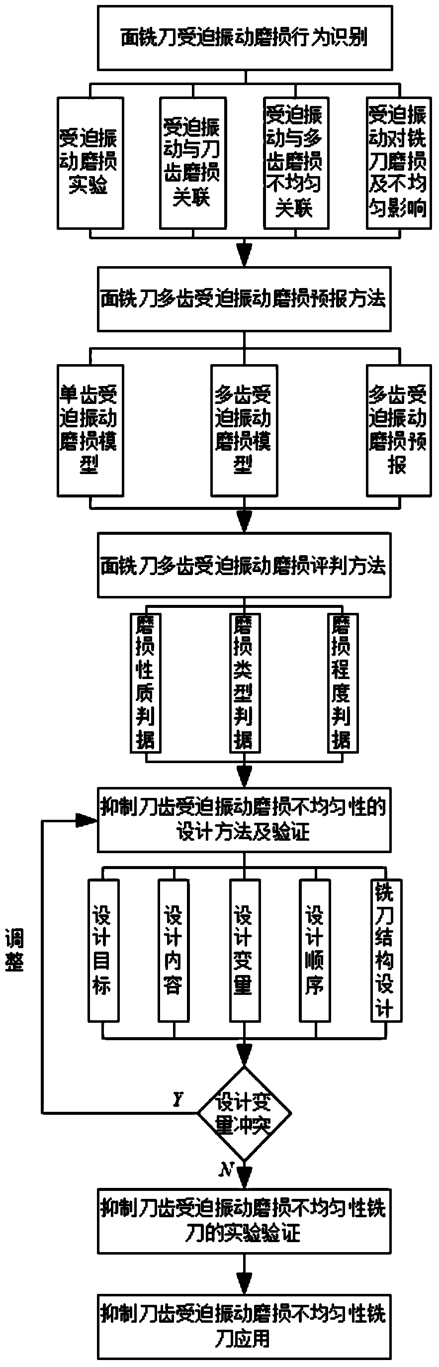
[0098] The specific steps of a high-speed milling cutter design method for suppressing the unevenness of forced vibration and wear of cutter teeth in this embodiment are as follows:

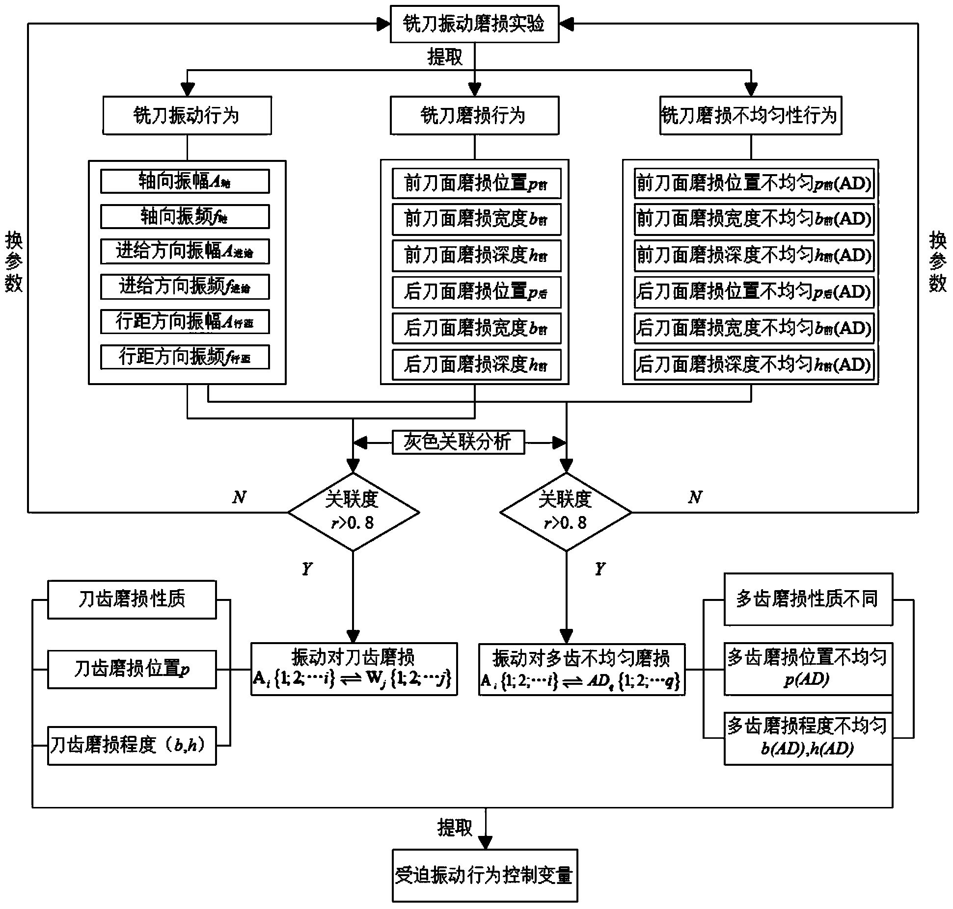
[0099] 1. Identification method of forced vibration wear of milling cutter

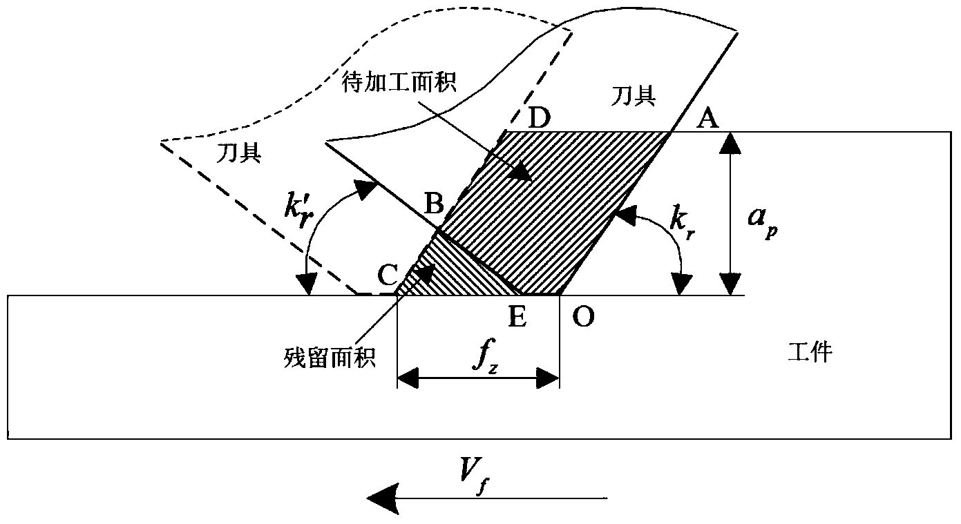
[0100] Due to the forced vibration of the process system in the milling process, as the cutting process continues, due to the mutual contact between the tool and the workpiece, the tool and the chips; they move with each other at a certain linear speed, and the vibration generates displacement at the same time, forming a process that accompanies the tool cutting process. The dynamic wear process, that is, the dynamic characteristics of the forced vibration of the milling cutter.

[0101] The forced vibration of the milling cutter will cause the forced vibration wear of the milling cutter t...


PUM


Abstract

The invention discloses a high-speed milling cutter designing method for suppressing unevenness in forced vibration wear of cutter teeth, and belongs to the technical field of cutters. The high-speed milling cutter designing method particularly includes providing a process for identifying forced vibration wear behavior of a milling cutter by the aid of correlation characteristics of forced vibration of the high-speed face milling cutter and wear behavior of the cutter teeth; building a multi-tooth forced vibration wear model of the milling cutter and providing a process for predicting and judging forced vibration wear and uneven wear of the milling cutter. The high-speed milling cutter designing method has the advantages that a process for controlling the uneven wear of the milling cutter and a process for designing the milling cutter are provided, so that the problem of design conflicts among multi-tooth wear positions, wear areas and wear depth control variables of an existing milling cutter can be solved, the milling cutter with the diameter of 63mm can be designed by the high-speed milling cutter designing method, the unevenness in forced vibration wear of the cutter teeth for cutting No.45 steel at high speeds can be effectively suppressed, and the high-speed milling cutter designing method is used for designing milling cutters.

Description

technical field [0001] The invention proposes a high-speed milling cutter design method for suppressing the unevenness of forced vibration and wear of cutter teeth, and specifically utilizes the correlation characteristics between the forced vibration of high-speed face milling cutters and the wear behavior of cutter teeth to provide the identification of forced vibration and wear behavior of milling cutters Methods: establish the multi-tooth forced vibration wear model of milling cutter, put forward the prediction and evaluation method of forced vibration wear and uneven wear of milling cutter; put forward the control method and design method of milling cutter uneven wear, and solve the problem of multi-tooth milling cutter The design conflicts of wear position, wear area, and wear depth control variables are designed. A 63 mm diameter milling cutter that can effectively suppress the uneven wear of forced vibration of No. 45 steel teeth in high-speed cutting is designed. Bac...

Claims


Application Information

Patent Timeline
Patent Type & Authority Applications(China)
IPC IPC(8): G06F17/50B25C5/00
Inventor 姜彬韩占龙陈强
Owner HARBIN UNIV OF SCI & TECH
Why Eureka
Try Eureka