
Beam combining device for multicolor semiconductor laser devices

A technology of semiconductors and lasers, applied in the field of multi-color semiconductor laser beam combining devices, can solve problems such as unguaranteed, channel interference, high yield, etc., and achieve the effects of guaranteed polarization performance, easy assembly and adjustment, and stable performance

Active Publication Date: 2014-04-30
PAVILION INTEGRATION CORP SUZHOU
View PDF5 Cites 6 Cited by
  • Summary
  • Abstract
  • Description
  • Claims
  • Application Information

AI Technical Summary

Problems solved by technology

[0003] Combining two or more laser beams through a beam combining device in free space is the most common method, with a relatively simple process and low cost; however, for applications with high noise requirements, there is no implementation advantage, and after beam combining The interference of each channel cannot be effectively reduced, and it is not convenient to add monitoring or feedback components to it
[0004] Combining two or more laser beams through a waveguide device is also widely used. The structure is simple, but the process requirements are high. Compared with free space, there is no cost advantage for combining beams through a beam combining device, and each channel The interference is serious, and a special process is required to ensure the polarization characteristics of the output beam
No cost advantage in applications sensitive to noise parameters and high polarization maintaining performance
[0005] Combining two or more laser beams through optical fiber fusion is currently used in many fields, but each time most of the fusion is two optical fibers. If it is a combination of multiple beams, the operation is complicated and cannot be guaranteed to be high. yield
Similar to the above two methods, there is no cost advantage in applications sensitive to noise parameters and high polarization maintaining performance

Method used


Image

  • Beam combining device for multicolor semiconductor laser devices
  • Beam combining device for multicolor semiconductor laser devices
  • Beam combining device for multicolor semiconductor laser devices

Examples


Embodiment

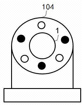
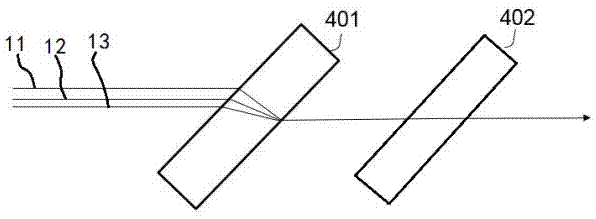
[0025] A kind of multi-color semiconductor laser beam combiner of the present embodiment, such as figure 1 As shown, it includes a first semiconductor laser 101, a second semiconductor laser 102 and a third semiconductor laser 103 with different wavelengths connected in parallel; corresponding to the first semiconductor laser 101, the second semiconductor laser 102 and the third semiconductor laser 103 respectively The first beam polarization improving device 21, the second beam polarization improving device 22 and the third beam polarization improving device 23 connected in parallel prevent the feedback of the same polarization part of the beam to reduce the increase of the resulting beam noise, and the beam The polarization improving devices 2 are respectively located on the output optical paths of the corresponding semiconductor lasers 1 . The beam combining mirror group 3 for beam combining, the input end of the beam combining mirror group 3 is located on the output optica...


PUM


Abstract

The invention discloses a beam combining device for multicolor semiconductor laser devices. The beam combining device comprises a plurality of the semiconductor laser devices which are connected in parallel and have different wave lengths, a plurality of light beam polarization improvement devices which are connected in parallel and arranged on the output light paths of the corresponding semiconductor laser devices respectively, and a beam combining mirror set used for beam combination, wherein the input ends of the beam combining mirror set are arranged on the output light paths of the light beam polarization improvement devices, and the output ends of the beam combining mirror set and a compensating mirror set are arranged on the same light path. The beam combining device for the multicolor semiconductor laser devices can effectively control the increase amount of the noise of beam combination of the multicolor semiconductor laser devices and guarantee the polarization performance of the light beams after beam combination, and has the advantages of being low in cost, easy to assemble and adjust, and stable in performance.

Description

technical field [0001] The invention relates to the field of semiconductor lasers, in particular to a multicolor semiconductor laser beam combiner. Background technique [0002] Because semiconductor lasers have the advantages of high efficiency, small size, and long life, modules that combine beams of semiconductor lasers are widely used in laser medical treatment, laser detection and measurement, and instrumentation. At present, there are mainly three methods for beam combining of semiconductor lasers: 1) combining two or more laser beams through a beam combining device in free space; 2) combining two or more laser beams through a waveguide device; 3) Combining two or more laser beams through optical fiber fusion. [0003] Combining two or more laser beams through a beam combining device in free space is the most common method, with a relatively simple process and low cost; however, for applications with high noise requirements, there is no implementation advantage, and a...

Claims


Application Information

Patent Timeline
Patent Type & Authority Applications(China)
IPC IPC(8): H01S5/40H01S5/06G02B27/28G02B27/10
Inventor 朱金通季朝华宫广彪倪秀付
Owner PAVILION INTEGRATION CORP SUZHOU
Learn More