
Control method and device for anti-glare lighting system

A control method and lighting system technology, which are applied in the control field of anti-glare lighting systems, can solve the problems of inability to suppress, heavy equipment, and no practicability, and achieve the effects of improving the glare suppression ratio and reducing attenuation.

Active Publication Date: 2018-06-19
张京涛
View PDF4 Cites 0 Cited by
  • Summary
  • Abstract
  • Description
  • Claims
  • Application Information

AI Technical Summary

Problems solved by technology

According to literature records, mechanical light valves were first applied to time-separated anti-glare lighting systems, but the equipment was heavy and impractical; later in the literature, the concept of liquid crystal light valves controlled by electronic control or single-chip microcomputer appeared, compared with the previous ones. , although the hardware has been improved, but limited by its control theory and method, there are the following defects and problems:
When the headlight pulses of both sides coincide, in order to avoid the headlight pulse of the other side, the lighting systems of the two vehicles will adopt the same method to change their own lighting time, causing the light pulses of both sides to overlap again, and so on. It is turned on synchronously, resulting in the failure of the anti-glare function
[0004] 2. In actual application, it only suppresses the glare caused by the headlights of the vehicles in front of the car when passing, but cannot suppress the glare caused by the headlights of overtaking vehicles in the rearview mirror.
[0005] The above shortcomings lead to the fact that although the time-separated anti-glare lighting system can play a role in reducing glare to a certain extent, its effect is not obvious, and it is still difficult to avoid danger.

Method used


Image

  • Control method and device for anti-glare lighting system
  • Control method and device for anti-glare lighting system
  • Control method and device for anti-glare lighting system

Examples


Embodiment 1

[0028] Embodiment 1 is the embodiment one of the control method.

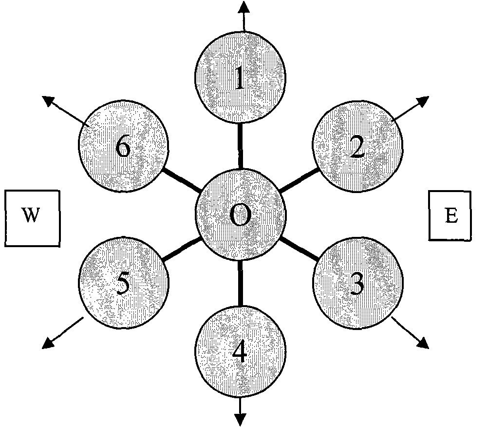
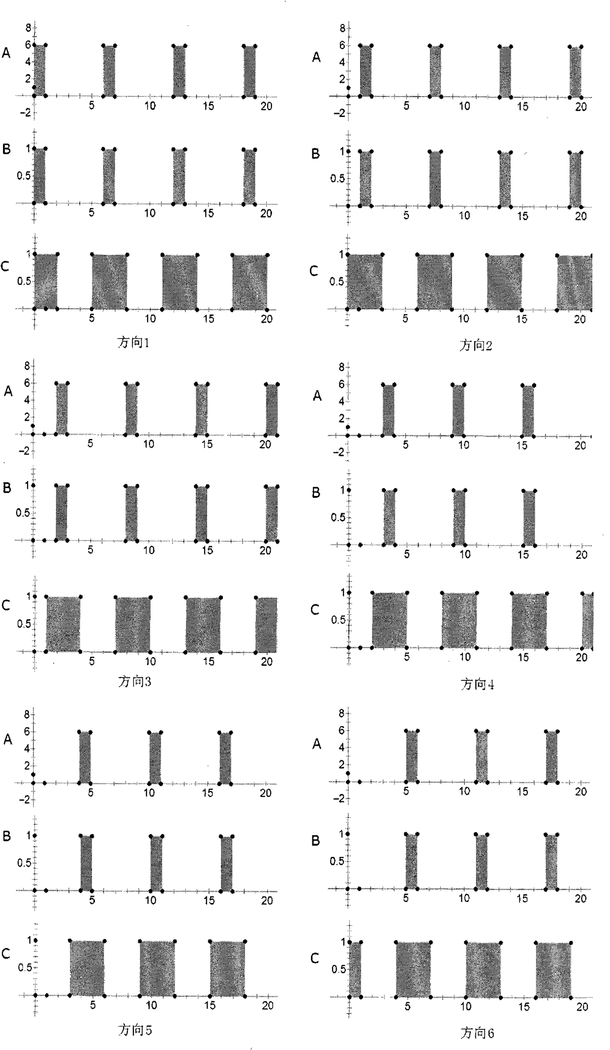
[0029] Divide the circular direction in the horizontal plane into several parts, and the specific number of parts will have a great impact on the performance of the system. If using faster light valves and lighting equipment, it can be divided into more parts, so as to obtain excellent anti-glare effect on common glare sources. In practical applications, an observation cycle can be divided into dozens, hundreds or even thousands of parts according to the performance of the device, so as to improve the anti-glare performance of the system. Here, for the convenience of description, temporarily set it as 6 parts, each 60°, and name each direction with numbers ( figure 1 ). The time of each observation cycle is also temporarily divided into 6 parts, which become 6 time periods. As far as possible, the lights in each direction only emit light during the corresponding time period of each lighting cycle.

[0030] ...

Embodiment 2

[0050] Embodiment 2 is the second embodiment of the control method.

[0051] In particular, the concepts of "Xiang Yuan" and "Time Yuan" are introduced. Firstly, divide the direction of a circle in the horizontal plane into several parts, and each part of direction is further divided into the smaller unit of direction "Xiang Yuan". The time of each observation period is divided into: a time unit "epoch" smaller than the implementation of the control method - a time period. According to the principle that the time of luminous lighting is associated with the direction of luminous lighting, it is stipulated that there is a one-to-one correspondence between the direction and the time, so as to establish a time cycle system corresponding to the direction of the week. The essence of an epoch can be regarded as a smaller time period of equal length. In the embodiment of the second control method, the lighting plan for the headlights to emit light under different lighting environmen...

Embodiment approach

[0063] Compared with the first embodiment of the control method, the second embodiment of the control method has the following advantages:

[0064] 1. The "time period" in the first embodiment can be regarded as a collection of a certain number of adjacent time units. That is to say, in the second embodiment, by setting a specific "pre-plan", the response mode and control method of the first embodiment system can be completely realized, and all the functions of the first embodiment can be realized. The first embodiment can be regarded as a special case of the second embodiment. That is to say, the scheme 2 system can contain all the working modes and functions of the scheme 1 system. All the advantages of the system of embodiment one are possessed.

[0065] 2. In the second implementation of the control method, the time element can be regarded as the subdivision of the time period for the light valve to be opened or closed, and this is the minimum control unit of the system,...


PUM


Abstract

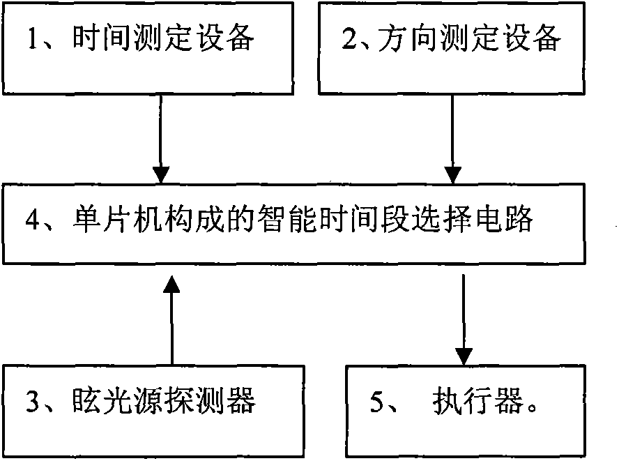
The invention discloses a control method and device for an anti-dazzle illuminating system. The method correlates the time and direction of luminous illumination, the direction of one circle in the horizontal plane of illuminating space is divided into a plurality of parts, meanwhile, the time of each observation period is divided into parts with the number equal to that of the parts of the direction, the direction parts correspond to the time frames one to one, lights emitting light in all the directions emit light and are observed in one or more corresponding time frames according to the site environment and the requirement for correlating the time and direction of the luminous illumination, the relation of the light emitting time frames and the observation time frames of various kinds of lamplight are set, and the lamplight of different purposes can be visible or invisible. The device adopting the control method is composed of an intelligent time frame selection circuit composed of time measuring equipment, direction measuring equipment and a single-chip microcomputer, a dazzle source detector and an actuator. The method and device can effectively prevent dazzle and guarantee driving safety to the maximum extent.

Description

technical field [0001] The invention relates to the technical field of automobile driving safety, in particular to a control method and device for an anti-glare lighting system. Background technique [0002] Time-separated anti-glare lighting system is a hot spot in the study of automotive anti-glare lighting. According to literature records, mechanical light valves were first applied to time-separated anti-glare lighting systems, but the equipment was heavy and impractical; later in the literature, the concept of liquid crystal light valves controlled by electronic control or single-chip microcomputer appeared, compared with the previous ones. , although the hardware has been improved, but limited by its control theory and method, there are the following defects and problems: [0003] 1. Unable to identify and solve the problem of the pulse overlap of the headlights of the other side and one's own side. In the past, the time-separated anti-glare lighting system only divid...

Claims


Application Information

Patent Timeline
Patent Type & Authority Patents(China)
IPC IPC(8): H05B37/02B60Q1/00
CPCY02B20/40
Inventor 张京涛
Owner 张京涛
Learn More