
Fixed wing propeller-driven aircraft and driving device thereof

A driving device and propeller technology, which is applied in the aviation field, can solve the problems affecting the opening of the umbrella cabin, interference, and misalignment of the center of gravity, and achieve the effects of extending the voyage and reducing energy consumption.

Active Publication Date: 2016-08-24
HOOAH AVIATION TECH CO LTD
View PDF9 Cites 0 Cited by
  • Summary
  • Abstract
  • Description
  • Claims
  • Application Information

AI Technical Summary

Problems solved by technology

The disadvantage is: the driving system conflicts with FPV (first person primary vision), that is, the most reasonable installation position of the camera is on the head of the fuselage, but the installation position of the camera is occupied by the driving system, and the installation position of the camera is at the center of the fuselage. The part behind the head causes the camera to be interfered by the drive system when collecting images, which reduces the quality of image collection
Disadvantages: The center of gravity of the aircraft is at the rear, resulting in the need for excess weight to balance the center of gravity, increasing the take-off weight and shortening the flight range
For example, the notification number is CN203612198, and the name is a utility model patent for a front-pull and rear-push multifunctional fixed-wing UAV. The power system of this UAV is arranged as follows: one of the power systems is placed high on the upper part of the fuselage , this method overcomes the problem that the power front pull power system affects the installation of the camera, and also avoids the problem that the power push back power system requires extra weight to balance the center of gravity and affects the opening of the parachute. However, the waist push power system is still There are the following defects: when the power system is placed high on the upper part of the fuselage, the push center line and the center of gravity line of the power system are misaligned (such as Figure 17 As shown), it is necessary to increase the wing elevation angle or change the thrust line to balance the center of gravity of the UAV, so as to ensure that the anti-UAV is straight and stable
However, the problem with the waist-push power system is that the thrust line of the power system is misaligned with the center of gravity of the fuselage. If this problem is solved, many problems of the UAV will be solved. Unfortunately, according to According to the applicant's knowledge of the development history of UAVs and the applicant's inquiries about relevant materials, no power waist-thrust fixed-wing UAVs have been found so far that the thrust line of the power system coincides with the center of gravity line. Therefore, this is also a problem that those skilled in the art have always wanted to solve but has not been solved

Method used


Image

  • Fixed wing propeller-driven aircraft and driving device thereof
  • Fixed wing propeller-driven aircraft and driving device thereof
  • Fixed wing propeller-driven aircraft and driving device thereof

Examples


no. 1 approach

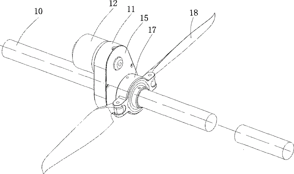
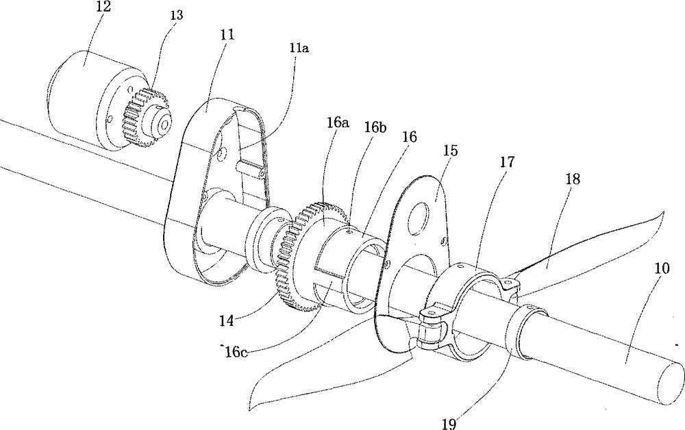
[0049] Such as figure 1 and figure 2 As shown, the driving device of the first fixed-wing propeller aircraft of the present invention includes a tail boom 10, a propeller and a driving mechanism. The tail boom 10 is made of carbon fiber material, and one end of the tail boom 10 is used to be fixedly connected with the fuselage of the drone. Therefore, the axis line of the tail boom 10 is on the same straight line as the center of gravity of the whole drone. The driving mechanism is arranged on the tail rod 10, and the axial direction of the power output end of the driving mechanism is on the same straight line as the axial direction of the tail rod 10. Therefore, after the power output end of the driving mechanism is fixedly connected with the propeller, the propeller The axial direction and the axial direction of the tail rod 10 are on the same straight line.

[0050] The drive mechanism includes a support base 11, a driver 12 and a transmission mechanism. The support bas...

no. 2 approach

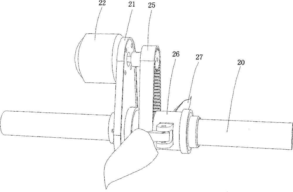
[0055] Such as image 3 and Figure 4 As shown, the driving device of the second fixed-wing propeller aircraft of the present invention includes a tail boom 20, a propeller and a driving mechanism. The tail boom 20 is made of carbon fiber material, and one end of the tail boom 20 is used to be fixedly connected with the fuselage of the drone. Therefore, the axis line of the tail boom 20 is on the same straight line as the center of gravity of the whole drone. The driving mechanism is arranged on the tail rod 20, and the axial direction of the power output end of the driving mechanism is on the same straight line as the axial direction of the tail rod 20. Therefore, after the power output end of the driving mechanism is fixedly connected with the propeller, the propeller The axial direction is on the same straight line as the axial direction of the tail rod 20 .

[0056] The drive mechanism includes a support base 21, a driver 22 and a transmission mechanism. The support base...

no. 3 approach

[0061] Such as Figure 5 Shown, the driving device of the third fixed-wing propeller aircraft of the present invention includes tail boom, propeller and driving mechanism. The tail rod is made of carbon fiber material. In this embodiment, the tail rod is composed of a first tail rod 30a and a second tail rod 30b, and the axes of the first tail rod 30a and the second tail rod 30b are on the same straight line , one end of the first tail rod 30a is used to connect the fuselage of the drone, and the other end of the first tail rod 30a is connected with the driving mechanism. The axes of the first tail boom 30a and the second tail boom 30b are on the same straight line as the center of gravity of the whole drone. The axial direction of the power output end of the driving mechanism is on the same straight line as the axial direction of the first tail rod 30a and the second tail rod 30b. Therefore, after the power output end of the driving mechanism is fixedly connected to the prop...


PUM


Abstract

The invention discloses a driving device of a fixed wing propeller-driven aircraft. The driving device comprises a tail rod, a propeller and a driving mechanism, wherein the axial direction of the propeller and the axial direction of the tail rod are on the same straight line, the driving mechanism is arranged on the tail rod, the axial direction of the power output end of the driving mechanism and the axial direction of the tail rod are located on the same straight line, and the power output end of the driving mechanism is fixedly connected with the propeller. Thrust lines generated by the driving device can coincide with the center of gravity line of an unmanned aerial vehicle.

Description

technical field [0001] The invention relates to the field of aviation technology, in particular to a fixed-wing propeller aircraft and a driving device thereof, wherein the driving device is mounted on the waist of the fixed-wing propeller aircraft. Background technique [0002] Fixed-wing UAV is a kind of fixed-wing propeller aircraft, and fixed-wing UAV is a kind of aircraft driven by power and unmanned on board. It usually consists of airframe, power plant, flight control and management equipment, launching and recovery equipment, etc. It can fly remotely or automatically, and can be used once, recycled, and used multiple times. It is one of today's high-tech equipment, widely used in many military operations such as battlefield reconnaissance, electronic countermeasures, post-war damage assessment, and ground attack. It is an indispensable equipment for information warfare. In the civilian field, it has been widely used in artificial precipitation, aerial remote sensing...

Claims


Application Information

Patent Timeline
Patent Type & Authority Applications(China)
IPC IPC(8): B64C11/00B64D35/00
Inventor 刘阳姚伟平周邦华
Owner HOOAH AVIATION TECH CO LTD
Learn More