Metering pump

A technology for metering pumps and pump chambers, applied in the direction of pumps, pump components, variable capacity pump components, etc., can solve the problems that hinder the compact structure of metering pumps, and achieve the effects of being conducive to manufacturing, simple fluid connection, and compact structure

Inactive Publication Date: 2014-04-30
THOMAS MAGNETE GMBH
View PDF8 Cites 4 Cited by
  • Summary
  • Abstract
  • Description
  • Claims
  • Application Information

AI Technical Summary

Problems solved by technology

Disadvantage is having a fluid channel around the sealed cylind

Method used


Image

  • Metering pump
  • Metering pump

Examples


Embodiment Construction

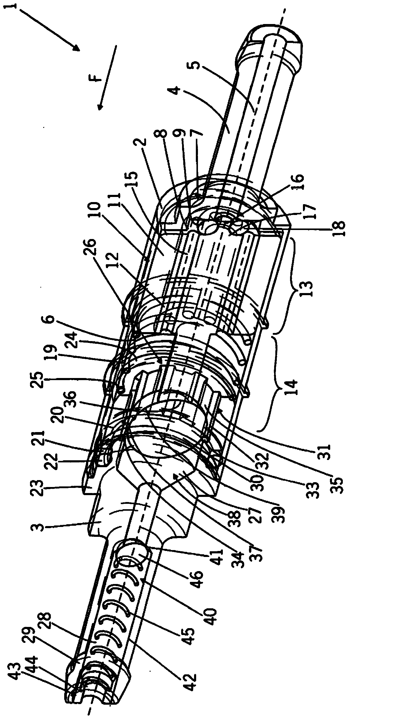
[0021] figure 1A first embodiment of a metering pump 1 constructed as a reciprocating piston pump is shown, comprising an inlet piece 2 forming a housing and an outlet piece 3 inserted longitudinally into the inlet piece 2 . The inlet piece 2 and the outlet piece 3 are bodies of revolution and are oriented concentrically to each other and form a common axis A with which the delivery direction F of the pump 1 from the inlet piece 2 to the outlet piece 3 is distributed. The inlet side of the inlet part 2 has an inlet connection 4 with an inlet channel 5 . For connection to the pipeline system, the inlet connector 4 has a thickened nozzle of the inlet connector 4 . In the outlet-side casing section 2a, the inlet part 2 is formed as a hollow cylinder, in the interior of which a cylindrical pump chamber 6 is arranged. The pump drive is arranged on the outside of the inlet part 2. The solenoid coil unit formed by coils and coil formers is not shown for better overview. The sleeve...


PUM


Abstract

The invention relates to a metering pump, the object of which is to enable simple fluid metering, to have an extended service life and to be of compact construction. Said metering pump is characterised in that the piston rod (12) is in operative connection with a control body (30) which has a circumferential sealing zone (37), in that the internal circumference of the sealing cylinder (20) radially surrounds the sealing zone (37), in that, on the piston rod side, a compensating zone (39), which is at a greater radial distance from the sealing cylinder (20) than the sealing zone (37), adjoins the sealing zone (37) at least in portions, and in that the control body (30), after passing beyond the control edge (34) in the actuation direction (F) of the actuator (10), at least largely severs the fluid connection.

Description

technical field [0001] The invention relates to a metering pump according to the preamble of claim 1 . Background technique [0002] DE 10 2004 028 889 A1 shows a metering pump comprising a sealing cylinder, a piston rod movable axially within the sealing cylinder, an outlet valve housing and an outlet valve body arranged on the outlet side of the sealing cylinder. At its outlet-side end, the sealing cylinder has a flange facing the inside, which has an edge directed toward the radial plane of the vehicle of the outlet valve housing, which edge forms the valve seat of the valve body. The sealing cylinder forms and includes a delivery chamber, wherein a spring arranged in the delivery chamber bears on the flange. The other end of the spring rests on the piston rod and pretensions the piston rod against the conveying direction. The inlet side of the cylinder element has slots extending axially from the pump chamber to the delivery chamber for the fluid connection. The slot ...

Claims


Application Information

Patent Timeline
IPC IPC(8): F04B13/00F04B53/14F04B53/16
CPCF04B53/16F04B17/044F04B13/00F04B53/143F04B53/14F04B53/162F04B53/144
Inventor 罗伯特·韦尔尼茨迈克·赫克阿克塞尔·穆勒迈克尔·穆勒安德列亚斯·门前
Owner THOMAS MAGNETE GMBH
Why Eureka
Try Eureka