X-ray generator and X-ray imaging apparatus
An X-ray and generator technology, applied in the field of transmission type X-ray generators, can solve problems such as low X-ray generation efficiency, and achieve the effect of improving X-ray generation efficiency
- Summary
- Abstract
- Description
- Claims
- Application Information
AI Technical Summary
Problems solved by technology
Method used
Image

Examples
no. 1 example
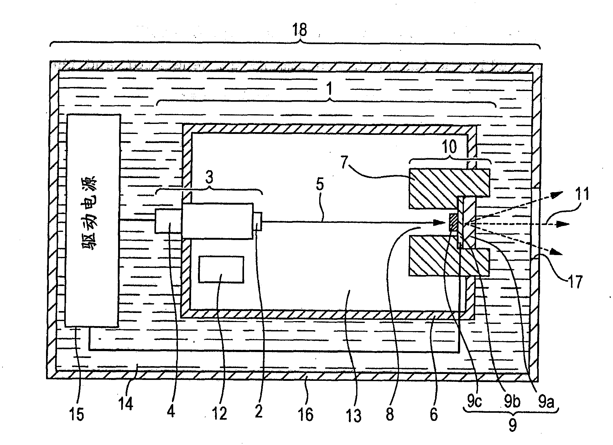
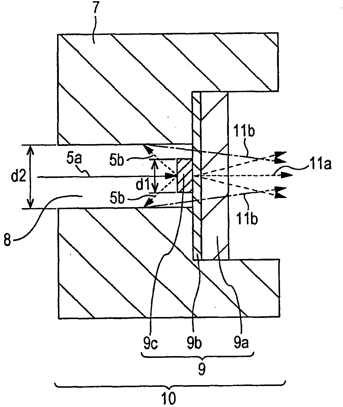
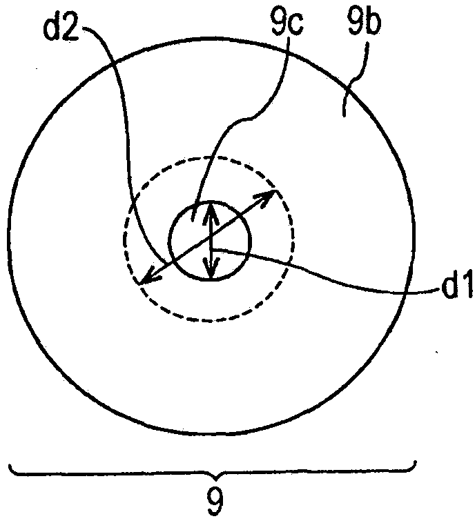
[0028] Figure 1A is a sectional view of an exemplary configuration of a transmission type X-ray generator (hereinafter, “X-ray generator”) 18 according to this embodiment. Figure 1B yes Figure 1A An enlarged cross-sectional view of anode 10 is shown. Figure 1C is viewed from the target side Figure 1A A plan view of the target area 9 is shown.
[0029] The X-ray generator 18 includes the X-ray source 1 and the driving power source 15 provided in the housing 16 and the insulating oil 14 filling the remaining space in the housing 16 . The housing 16 has an X-ray extraction window 17 .
[0030] The X-ray source 1 includes an electron source 3 , an anode 10 , a getter 12 and a vacuum container 6 .
[0031] The electron source 3 includes a current introduction terminal 4 and an electron emission portion 2 . The mechanism of the electron source 3 for emitting electrons may be any electron source capable of controlling the amount of electrons emitted from the outside of the va...
no. 2 example
[0053] will refer to the attached Figure 2A and Figure 2B A second embodiment is described. Figure 2A is a cross-sectional view of a target region in the transmission type X-ray generator of this embodiment. Figure 2B is viewed from the target side Figure 2A A floor plan of the target area.
[0054]The X-ray generator of this embodiment has the same components as the first embodiment, and has the same configuration as the first embodiment except for the target area 9 . Such as Figure 2A As shown, the target area 9 is configured such that a target 9c is provided at a central area on the substrate 9a, and a conductive layer 9b is provided on the substrate 9a in an area other than the central area. The target 9c is connected to the conductive layer 9b. The materials of the substrate 9a, the conductive layer 9b and the target 9c can be selected in the same manner as described in the first embodiment.
no. 3 example
[0056] Figure 2C is a cross-sectional view of the target area in the X-ray generator of this embodiment. Figure 2D is viewed from the target side Figure 2C A floor plan of the target area.
[0057] The X-ray generator of this embodiment has the same components as the first embodiment, and has the same configuration as the first embodiment except for the target area 9 . Such as Figure 2C As shown, the target area 9 of this embodiment is configured such that the target 9c is provided at the central area on the substrate 9a, and the conductive layer 9b is provided on the substrate 9a and at the target in areas other than the central area. on 9c. The target 9c is covered by a conductive layer 9b. The materials of the substrate 9a, the conductive layer 9b and the target 9c can be selected in the same manner as described in the first embodiment.
PUM
 Abstract
Description
Claims
Application Information
 - Generate Ideas
- Intellectual Property
- Life Sciences
- Materials
- Tech Scout
- Unparalleled Data Quality
- Higher Quality Content
- 60% Fewer Hallucinations
Browse by: Latest US Patents, China's latest patents, Technical Efficacy Thesaurus, Application Domain, Technology Topic, Popular Technical Reports.
© 2025 PatSnap. All rights reserved.Legal|Privacy policy|Modern Slavery Act Transparency Statement|Sitemap|About US| Contact US: help@patsnap.com