Medical grinding cutter

A grinding and cutting tool technology, applied in medical science, surgery, etc., can solve the problems of tool movement interference, increase tool radius, complex structure, etc., and achieve the effect of reducing treatment cost, shortening recovery period, and simple transmission structure

Active Publication Date: 2014-05-07
CHONGQING XISHAN SCI & TECH
View PDF7 Cites 37 Cited by
  • Summary
  • Abstract
  • Description
  • Claims
  • Application Information

AI Technical Summary

Problems solved by technology

Since the grinding head is directly driven by the power handle, and the grinding head extends into the inside of the human body; it is difficult to control the grinding head for deep surgical sites; especially for different grinding parts, it is impossible to control the grinding head to change the grinding head by external force. Cutting the part, the use cannot be flexible and convenient, and the operation efficiency is low
[0003] In order to solve the above problems, a bendable grinding head has appeared, which can adapt to the change of the grinding part by controlling the pitching movement of the grinding head; the grinding head of this structure uses a universal joint for connection and transmission, and the structure and manufacturing process are complex, and The radius of the tool is increased, and the above-mentioned operations in orthopedics generally require the overall outer diameter of the grinding tool to be small, otherwise the tool cannot reach the surgical site or motion interference occurs during the operation
At the same time, in this structure, in order to realize the simultaneous pitching motion and rotation transmission between the grinding head and the inner cutter tube, the connection structure of the universal head is used, the structure is complicated and the control is unstable; and this structure only has pitching motion, which cannot realize The adaptive operation after changing the grinding part in the circumferential direction is to turn the tool and the driving handle as a whole, which is very inconvenient to use; moreover, the driving parts for driving the pitching are also relatively primitive, which affects the compactness of the tool

Method used


Image

  • Medical grinding cutter
  • Medical grinding cutter
  • Medical grinding cutter

Examples


Embodiment Construction

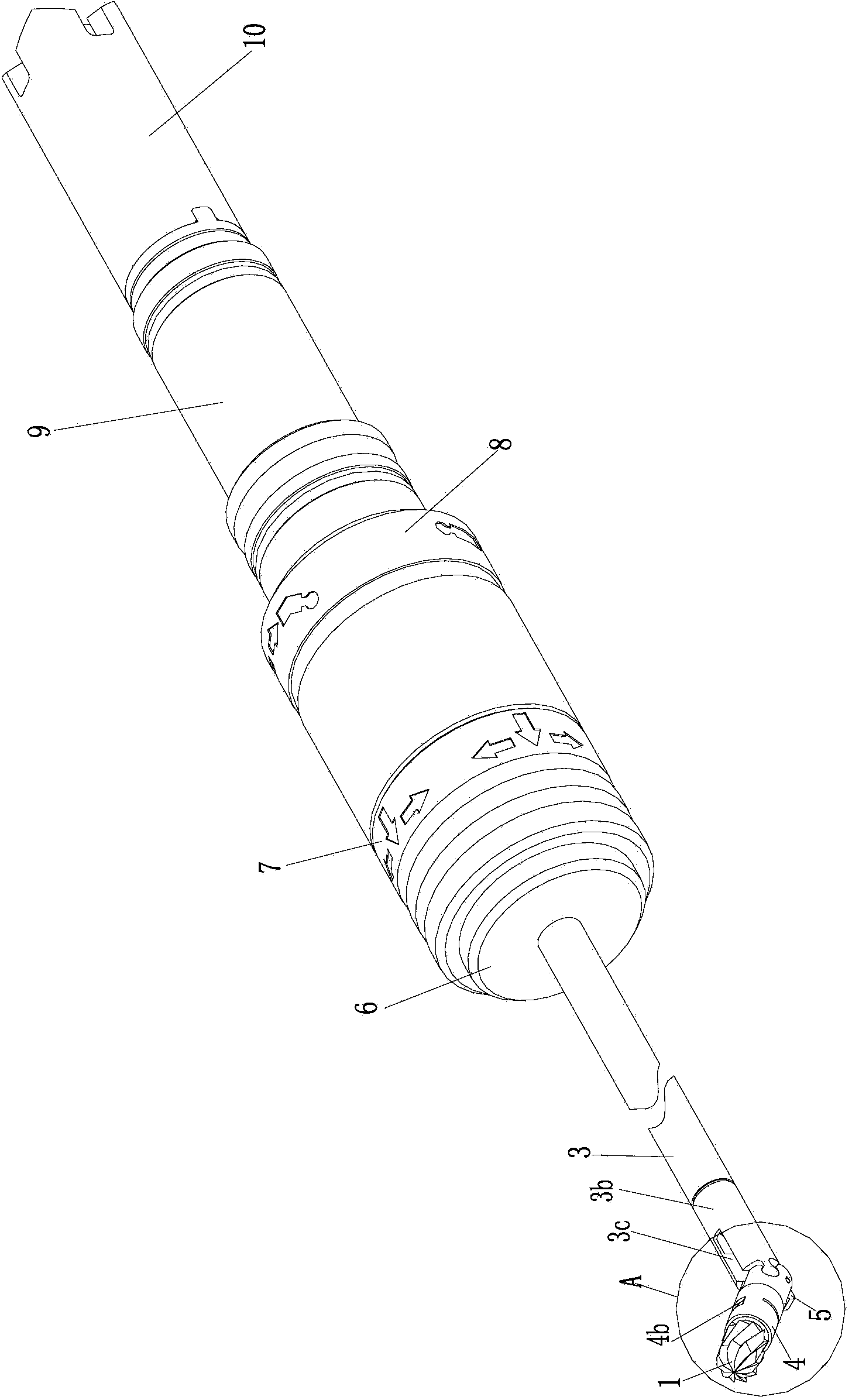
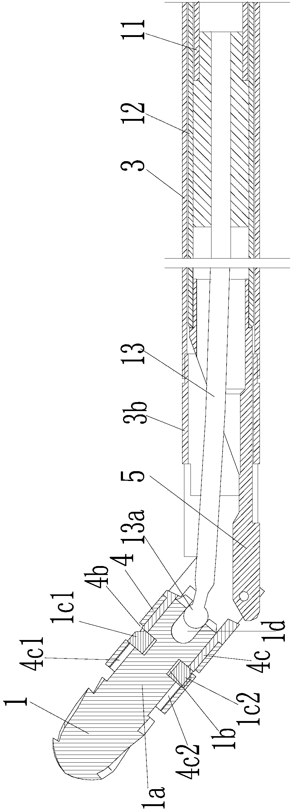
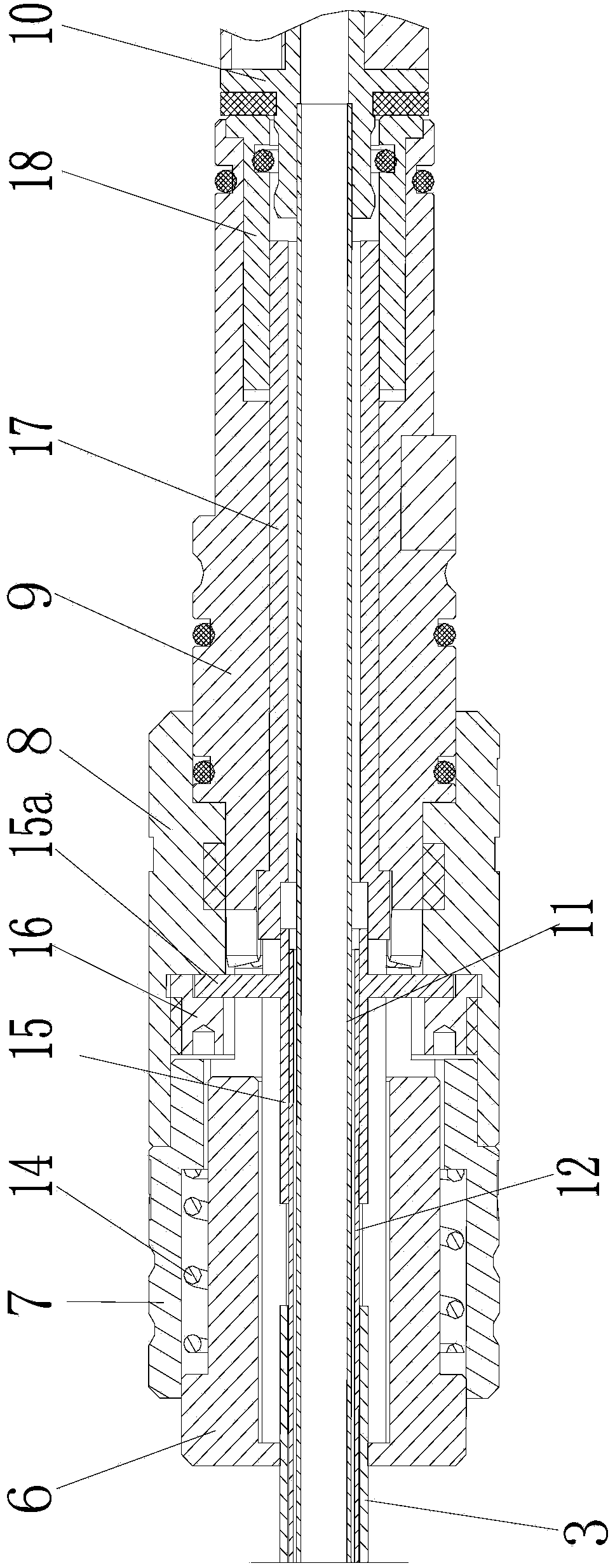
[0030] figure 1 It is a structural schematic diagram of the present invention, figure 2 It is a sectional view of the front section of the present invention, image 3 It is a sectional view of the rear section of the present invention, Figure 4 for figure 1 Enlarged view at A, Figure 5 is the structure diagram of the grinding head, Figure 6 It is a structural diagram of the flexible transmission section, as shown in the figure: it includes a knife tube assembly and a grinding head 1 installed at the front end of the knife tube assembly. The grinding head 1 is set in a manner that can be driven to pitch and rotate. The knife tube assembly It includes an outer knife tube 3 and an inner knife tube 11 coaxially rotating and fitted inside the outer knife tube and cooperating with the grinding head. The inner knife tube 11 is at least located at its front end and is provided with a flexible transmission section 13 for being hinged with the tail end of the grinding head 1 an...


PUM


Abstract

The invention discloses a medical grinding cutter. The cutter comprises a knife tube component and a grinding head, wherein the grinding head is mounted at the front end of the knife tube component; the grinding head can be driven for pitching and self-rotation; the tail end of the grinding head in the circumference direction is hinged to an inner knife tube in a transmission manner; a flexible transmission section is positioned at the front end of the inner knife tube and used to be hinged to the tail end of the grinding head, and can transfer torque. According to the invention, the medical grinding cutter adopts a direct hinging structure to transfer the transmission between the inner knife tube and the grinding head, can conduct a pitching motion, and adopts a flexible transmission structure to compensate axial deviation caused by pitching and transmission; the transmission structure is simple, and the transmission chain is shorter, which facilitates stable control, so that the operative efficiency is improved; the medical grinding cutter also adopts a structure capable of adjusting both the pitching and circumferential positions of the grinding head, so that the universal orientation adjustment is realized; the medical grinding cutter has a good adaptation to an operative site and higher precision; the operative process efficiency can be improved; the pain of the patients can be minimized, and meanwhile, the treatment cost can be reduced.

Description

technical field [0001] The invention relates to a medical device, in particular to a medical grinding tool for orthopedic surgery. Background technique [0002] In the process of orthopedic surgery, it is sometimes necessary to grind the bone tissue in the body; in the prior art, the power handle is generally used to directly drive the grinding head to rotate for grinding. Since the grinding head is directly driven by the power handle, and the grinding head extends into the inside of the human body; it is difficult to control the grinding head for deep surgical sites; especially for different grinding parts, it is impossible to control the grinding head to change the grinding head by external force. Cut the position, use can not realize flexible and convenient, and operation efficiency is lower. [0003] In order to solve the above problems, a bendable grinding head has appeared, which can adapt to the change of the grinding part by controlling the pitching movement of the ...

Claims


Application Information

Patent Timeline
Patent Type & Authority Applications(China)
IPC IPC(8): A61B17/16
CPCA61B17/16A61B2017/1602
Inventor 郭毅军柳长风
Owner CHONGQING XISHAN SCI & TECH
Why Eureka
Try Eureka