Medical grinding tool

A grinding and cutting tool technology, applied in medical science, dentistry, dental drilling, etc., can solve the problems of tool movement interference, inconvenient use, unstable control, etc., to reduce treatment costs, improve surgical efficiency, and facilitate stable control. Effect

Active Publication Date: 2016-12-14
CHONGQING XISHAN SCI & TECH
View PDF5 Cites 0 Cited by
  • Summary
  • Abstract
  • Description
  • Claims
  • Application Information

AI Technical Summary

Problems solved by technology

Since the grinding head is directly driven by the power handle, and the grinding head extends into the inside of the human body; it is difficult to control the grinding head for deep surgical sites; especially for different grinding parts, it is impossible to control the grinding head to change the grinding head by external force. Cutting the part, the use cannot be flexible and convenient, and the operation efficiency is low
[0004] In order to solve the above problems, a bendable grinding head has appeared, which can adapt to the change of the grinding part by controlling the pitching movement of the grinding head; the grinding head of this structure uses a universal joint for connection and transmission, and the structure and manufacturing process are complicated, and The radius of the cutter is increased, and the above-mentioned operations in orthopedics generally require the overall outer diameter of the grinding cutter to be small, otherwise the cutter cannot reach the surgical site or motion interference occurs during the operation
At the same time, in this structure, in order to realize the simultaneous pitching motion and rotation transmission between the grinding head and the inner cutter tube, the connection structure of the universal head is used, the structure is complicated and the control is unstable; and this structure only has pitching motion, which cannot realize The adaptive operation after changing the grinding part in the circumferential direction is to turn the tool and the driving handle as a whole, which is very inconvenient to use; moreover, the driving parts for driving the pitching are also relatively primitive, which affects the compactness of the tool

Method used


Image

  • Medical grinding tool
  • Medical grinding tool
  • Medical grinding tool

Examples


Embodiment Construction

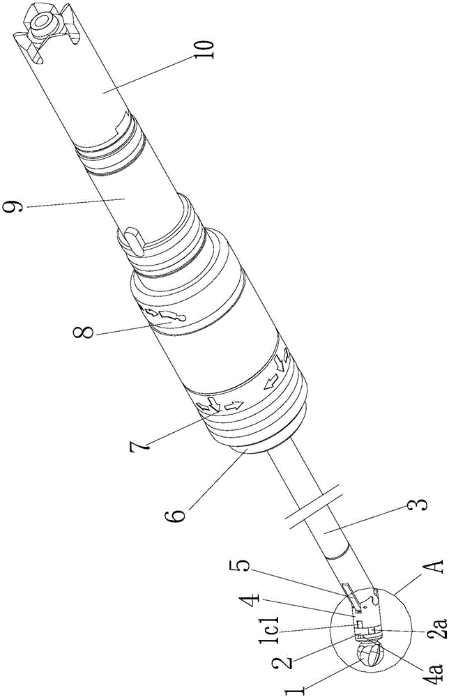
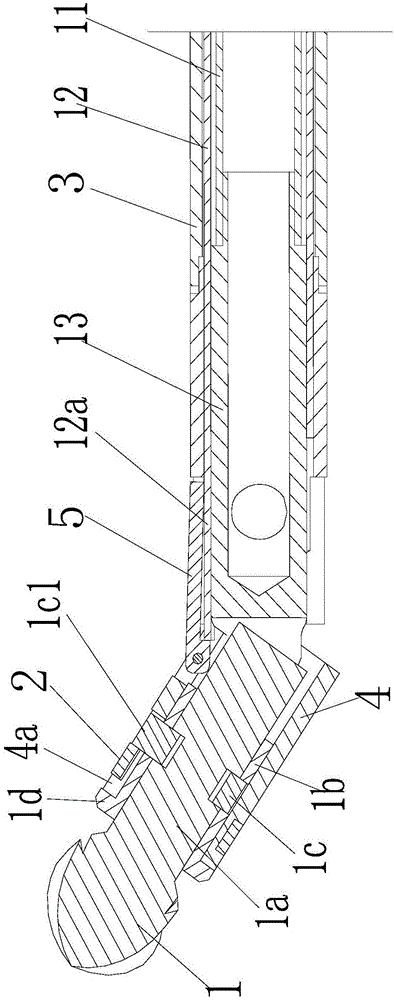
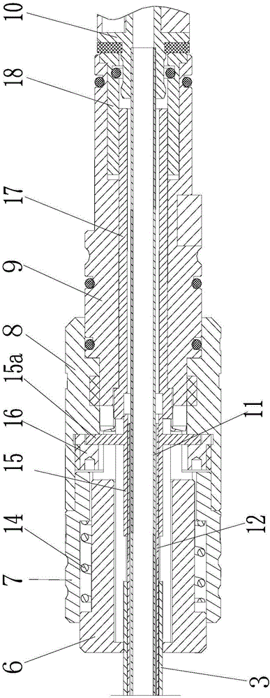
[0023] figure 1 It is a structural schematic diagram of the present invention, figure 2 It is a sectional view of the front section of the present invention, image 3 It is a sectional view of the rear section of the present invention, Figure 4 is the structure diagram of the grinding head, Figure 5 for figure 1 Enlarged view at A, Figure 6 For the purpose of hinged grinding head and inner knife tube, as shown in the figure: the medical grinding tool of this embodiment includes a knife tube assembly and a grinding head 1 installed on the front end of the knife tube assembly, and the grinding head 1 can be driven Pitch, rotation and revolution are set up; pitch refers to the rotation at a certain angle relative to the axis of the cutter tube assembly, autorotation refers to the rotation of the grinding head for grinding under the drive, and revolution refers to the movement of the entire grinding head around the cutter tube assembly The axis rotates to achieve the purp...


PUM


Abstract

The invention discloses a medical grinding tool, which comprises a tool tube assembly and a grinding head mounted at the front end of the tool tube assembly; the grinding head can be arranged in a mode of being driven to pitch and automatically rotate; and the grinding head further can be arranged in a mode of being driven to revolve. According to the medical grinding tool disclosed by the invention, the grinding head can be arranged in the mode of being driven to revolve, can carry out pitching motion, is simple in structure and is beneficial for stable control, so that operation efficiency is improved; with the adoption of the structure capable of enabling the grinding head to carry out pitching motion, and regulating a peripheral direction, universal direction regulation of the grinding head is realized; in an operation process, position regulation in the longitudinal direction and the peripheral direction of the grinding head can be realized according to changes of operation orientation, so that the medical grinding tool has relatively good adaption to an operation site; and the mechanical grinding tool has relatively high precision, improves efficiency of the operation process, shortens the recovery cycle after operation, relieves pains of patients, and also reduces treatment cost.

Description

[0001] The present invention is a divisional application of the patent application titled: Medical Grinding Tool and Drive Assembly, with the filing date: December 3, 2013, and the application number: 201310641876.X. technical field [0002] The invention relates to a medical device, in particular to a medical grinding tool for orthopedic surgery. Background technique [0003] In the process of orthopedic surgery, it is sometimes necessary to grind the bone tissue in the body; in the prior art, the power handle is generally used to directly drive the grinding head to rotate for grinding. Since the grinding head is directly driven by the power handle, and the grinding head extends into the inside of the human body; it is difficult to control the grinding head for deep surgical sites; especially for different grinding parts, it is impossible to control the grinding head to change the grinding head by external force. Cut the position, use can not realize flexible and convenient...

Claims


Application Information

Patent Timeline
Patent Type & Authority Applications(China)
IPC IPC(8): A61B17/16A61B17/32A61C1/18A61B17/29
CPCA61B17/16A61B17/1622A61B17/1624A61B17/1628A61B17/1631A61B17/1633A61B17/1659A61B17/32A61B17/32002A61B2017/2927A61B2017/564A61C1/188
Inventor 郭毅军张金彬柳长风
Owner CHONGQING XISHAN SCI & TECH
Why Eureka
Try Eureka