Medical grinding tool and driving assembly

A driving component and grinding technology, which is applied in the field of medical devices, can solve problems such as tool movement interference, increased tool radius, and inconvenient use, and achieve the effects of reducing treatment costs, shortening recovery periods, and improving surgical efficiency

Active Publication Date: 2015-05-13
CHONGQING XISHAN SCI & TECH
View PDF4 Cites 19 Cited by
  • Summary
  • Abstract
  • Description
  • Claims
  • Application Information

AI Technical Summary

Problems solved by technology

Since the grinding head is directly driven by the power handle, and the grinding head extends into the inside of the human body; it is difficult to control the grinding head for deep surgical sites; especially for different grinding parts, it is impossible to control the grinding head to change the grinding head by external force. Cutting the part, the use cannot be flexible and convenient, and the operation efficiency is low
[0003] In order to solve the above problems, a bendable grinding head has appeared, which can adapt to the change of the grinding part by controlling the pitching movement of the grinding head; the grinding head of this structure uses a universal joint for connection and transmission, and the structure and manufacturing process are complex, and The radius of the tool is increased, and the above-mentioned operations

Method used


Image

  • Medical grinding tool and driving assembly
  • Medical grinding tool and driving assembly
  • Medical grinding tool and driving assembly

Examples


Embodiment Construction

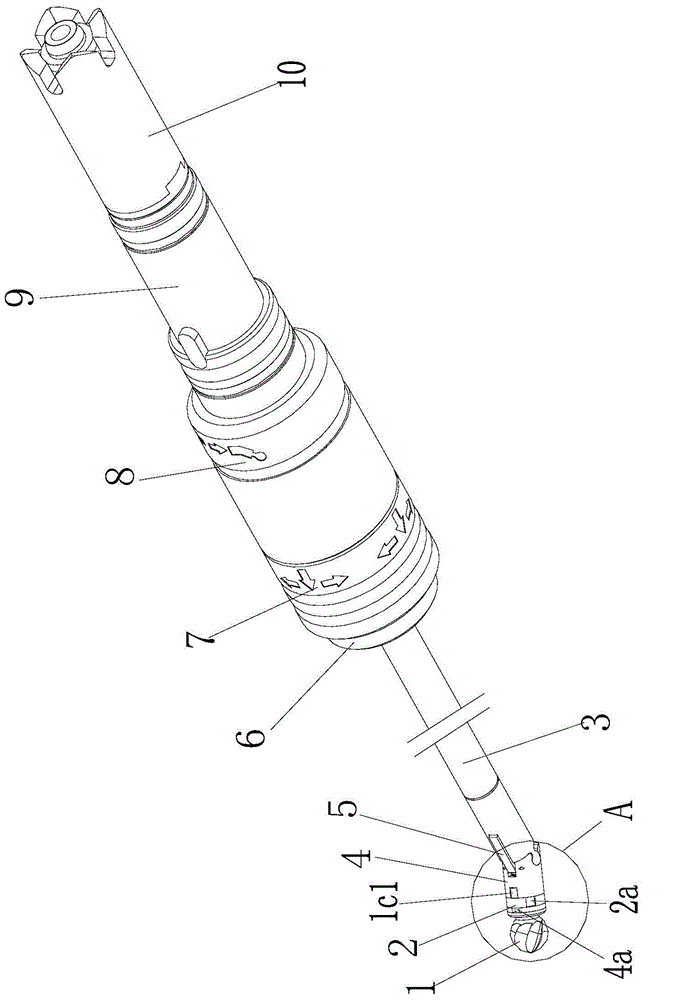
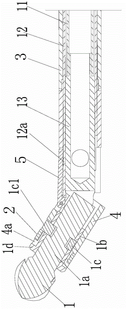
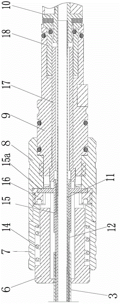
[0029] figure 1 It is a structural schematic diagram of the present invention, figure 2 It is a sectional view of the front section of the present invention, image 3 It is a sectional view of the rear section of the present invention, Figure 4 is the structure diagram of the grinding head, Figure 5 for figure 1 Enlarged view at A, Figure 6 For the purpose of hinged grinding head and inner knife tube, as shown in the figure: the medical grinding tool of this embodiment includes a knife tube assembly and a grinding head 1 installed on the front end of the knife tube assembly, and the grinding head 1 can be driven Pitch, rotation and revolution are set up; pitch refers to the rotation at a certain angle relative to the axis of the cutter tube assembly, autorotation refers to the rotation of the grinding head for grinding under the drive, and revolution refers to the movement of the entire grinding head around the cutter tube assembly The axis rotates to achieve the purp...


PUM


Abstract

The invention discloses a medical grinding tool and a driving assembly. The tool comprises a tool pipe assembly and a grinding head at the front end of the tool pipe assembly, the grinding head can be arranged in the mode of being capable of being driven to pitch and rotate, the tail end of the grinding head is hinged to an inner tool pipe in the mode of transmission in the circumferential direction, and the grinding head in the hinge structure has axial moving margin relative to the inner tool pipe. The direct hinge structure is adopted to transmit transmission between the inner tool pipe and the grinding head, pitching motion can be done, the structure is simple, a transmission chain is short, stable control is facilitated, and therefore operation efficiency is improved. The structure that the pitching and circumferential positions of the grinding head both can be adjusted is adopted, universal orientation adjustment of the grinding head is achieved, in the operation process, the grinding head can achieve longitudinal and circumferential position adjustment according to changes of operation orientation, the medical grinding tool has good orientation on a surgical spot, good precision is achieved, the efficiency of the operation process is improved, the postoperative recovery cycle is shortened, the pain of a patient is relieved, and meanwhile treatment cost is lowered.

Description

technical field [0001] The invention relates to a medical device, in particular to a medical grinding tool and a driving assembly for orthopedic surgery. Background technique [0002] In the process of orthopedic surgery, it is sometimes necessary to grind the bone tissue in the body; in the prior art, the power handle is generally used to directly drive the grinding head to rotate for grinding. Since the grinding head is directly driven by the power handle, and the grinding head extends into the inside of the human body; it is difficult to control the grinding head for deep surgical sites; especially for different grinding parts, it is impossible to control the grinding head to change the grinding head by external force. Cut the position, use can not realize flexible and convenient, and operation efficiency is lower. [0003] In order to solve the above problems, a bendable grinding head has appeared, which can adapt to the change of the grinding part by controlling the pi...

Claims


Application Information

Patent Timeline
IPC IPC(8): A61B17/16
CPCA61B17/16A61B17/1622A61B17/1624A61B17/1628A61B17/1631A61B17/1633A61B17/1659A61B17/32A61B17/32002A61B2017/2927A61B2017/564A61C1/188
Inventor 郭毅军张金彬柳长风
Owner CHONGQING XISHAN SCI & TECH
Why Eureka
Try Eureka