
Microporous laser pellet processing method and device based on temperature rise regulation and control

A laser processing method and target shot technology, applied in laser welding equipment, metal processing equipment, manufacturing tools, etc., can solve the problems of inability to process non-metallic materials, low processing efficiency, micro-cracks in the target shot, and easy control of processing parameters. , to ensure stability, the effect of small heat affected zone

Active Publication Date: 2014-05-07
HARBIN INST OF TECH
View PDF9 Cites 15 Cited by
  • Summary
  • Abstract
  • Description
  • Claims
  • Application Information

AI Technical Summary

Benefits of technology

This patented technical solution describes how thermal energy controls the temperatures used for machining materials such as metal or ceramic powders into holes made up of tiny particles called welds. By controlling this temperature, it helps prevent damage to any layers within these holes while still allowing them to function properly. Additionally, there are various techniques described where the coolant flows around the interior of the tool's chamber before reaching its destination (the end). These processes help improve precision and reduce waste compared to traditional methods like cutting tools.

Problems solved by technology

This patented describes various techniques for creation of highly accurate particle targets called atomic nuclei or plasma nucleuses through advanced control systems such as those described earlier. However, current processes require expensive equipment like ionized gas sources, ultrahigh pressure machines, and powerful lasers. Therefore, these conventional approaches face challenges due to complexity and cost issues associated with each method individually.

Method used


Image

  • Microporous laser pellet processing method and device based on temperature rise regulation and control
  • Microporous laser pellet processing method and device based on temperature rise regulation and control

Examples


Embodiment 1

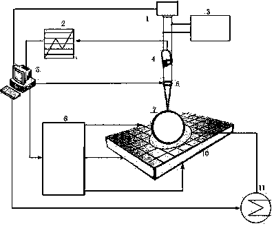
[0036] A microhole laser processing method for target pellets based on temperature rise regulation:

[0037] Drill holes in the target pellets with ultraviolet laser, ultrashort pulse laser or femtosecond laser;

[0038] Adjust the repetition frequency, power and pulse width of the laser through the laser power supply;

[0039] Real-time monitoring of pellet processing through high-resolution CCD;

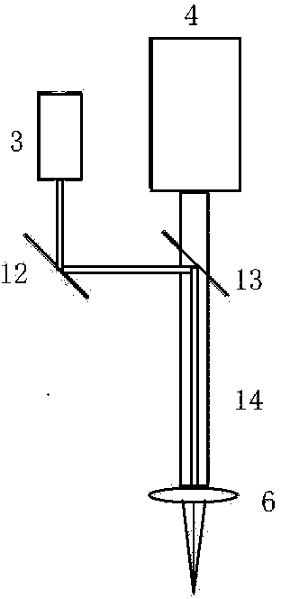
[0040] Use a microscope objective to focus the laser on the surface of the target pellet to be processed;

[0041] The target pellet is placed on the suction cup with heating function, and the three-dimensional precision micro-motion table on the suction cup is controlled to move along the three directions of X / Y / Z to realize the micro-motion adjustment of the target pellet;

[0042] The temperature of the heating sucker is adjusted by the temperature control system, and the temperature of the target is controlled, so that the pressure generated by the internal pres...

Embodiment 2

[0044] In the method of micro-hole laser processing of target pellets based on temperature rise control described in Example 1, when the ultraviolet laser is used to drill holes in the target pellets, the material of the target pellets with a fixed size is etched away by controlling the number of laser pulses.

Embodiment 3

[0046] In the method for processing target pellet micropores based on temperature rise regulation described in embodiment 1 or 2, the laser used is ultraviolet laser, ultrashort pulse laser or femtosecond laser, and when it interacts with the target pellet, photothermal and photochemical ablation occur. , to precisely control the erosion amount of the micropores of the target pellet.


PUM


Abstract

The invention discloses a microporous laser pellet processing method and a device based on temperature rise regulation and control. Micro cutting plays an important role in micro-target structure manufacturing, but the processing efficiency is low, and contact force can be generated; therefore, micro cracks are easily caused on a pellet; in a working process, cuttings, slag and the like enter the cavity of the pellet, so that the cuttings and the slag in the pellet cannot be removed thoroughly, and the subsequent use of the pellet is affected. The method disclosed by the invention comprises the steps of perforating the pellet by ultraviolet laser, ultrashort pulse laser or femtosecond laser; adjusting the repeating frequency, the power and the pulse width of laser through a laser device power supply; monitoring the pellet processing condition in real time through a high-resolution CCD (charge coupled device); focusing laser to the surface of the pellet to be processed through a microscope; placing the pellet onto a sucking disk with a heating function, controlling a three-dimensional precision micro workbench on the sucking disk to move in three directions, X, Y and Z to realize micro adjustment on the pellet. The microporous laser pellet processing method and the device are used for processing under a condition of preventing the cuttings and the slag from entering the pellet.

Description


Claims


Application Information

Patent Timeline
Owner HARBIN INST OF TECH
Features
  • Generate Ideas
  • Intellectual Property
  • Life Sciences
  • Materials
  • Tech Scout
  • Unparalleled Data Quality
  • Higher Quality Content
  • 60% Fewer Hallucinations
Learn More