Multi-objective optimization method of engine mounting system

An engine mount, multi-objective optimization technology, applied in the fields of motor vehicles, special data processing applications, instruments, etc.

Active Publication Date: 2014-05-07
HUNAN UNIV
View PDF0 Cites 31 Cited by
  • Summary
  • Abstract
  • Description
  • Claims
  • Application Information

AI Technical Summary

Problems solved by technology

At present, there is no research and patent on the optimization of engine mounts combining static and dynamic

Method used


Image

  • Multi-objective optimization method of engine mounting system
  • Multi-objective optimization method of engine mounting system
  • Multi-objective optimization method of engine mounting system

Examples


Embodiment Construction

[0066] The present invention will be further described in detail below through an example in conjunction with the accompanying drawings.

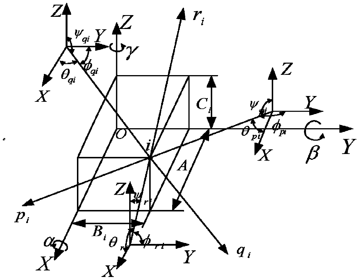
[0067] established as figure 1 The general layout space of the engine mount system is shown, where the i point is the i-th mount point, O is the public center of mass of the powertrain, OXYZ is the reference coordinate system taken by the research object of this paper, and the public center of mass is taken, Pointing to the direction of the cab (perpendicular to the crankshaft) is the X direction, pointing to the front end of the engine, parallel to the crankshaft is the Y direction, and vertically upwards is the Z direction. α, β, γ are the rotation angles of the suspension system around the OX axis (roll), OY axis (pitch) and OZ axis (yaw) respectively in the reference coordinate system (take the direction of the vector arrow as positive). A i , B i 、C i is the arrangement position of any (i-th one in the figure) suspended in the refe...


PUM


Abstract

The invention discloses a multi-objective optimization design method of an engine mounting system by overall consideration on mode decoupling and dynamic response characteristics. According to the method, a dynamical model of the engine mounting system is firstly established, then an oscillatory differential equation of the mounting system is obtained according to a multi-degree of freedom oscillation theory, an objective function is established according to an energy method decoupling theory and the dynamic response characteristics by solving the differential equation, the maximum decoupling rate in the vertical direction and the minimum amplitude of the sum of dynamical reaction forces of four mounts in all directions are used as objectives respectively, rigidity in each direction of the four mounts is selected as an optimization design variable, the limit of the decoupling rate around a bent axle and the response limit of the sum of reaction torques of all mounts around the bent axle are further added on the basis of the limit of inherent frequency, mount rigidity and power assembly displacement, then, multi-objective optimization is performed by a non-dominated sorting genetic algorithm, and finally, the feasibility of the method is verified through a detailed example. The optimization design method of the engine mounting system is high in integrity and practicability.

Description

technical field [0001] The invention belongs to the field of automobile structure optimization and relates to a multi-objective optimization method for an engine mount system. Background technique [0002] The engine is one of the main vibration sources of the vehicle. Due to the cyclical working of the internal combustion engine and the reciprocating nature of the moving mechanism, the vibration of the engine is inevitable. With the continuous improvement of the road surface level and the further improvement of other assemblies, the vibration problem of the engine becomes more and more prominent, which makes the vibration isolation design of the engine very important. In order to reduce the transmission of engine vibration to the human body, an engine mount system appears. For the engine, its six natural mode shapes are coupled in multiple degrees of freedom directions, which expands the resonance frequency range and makes the vibration response direction no longer single,...

Claims


Application Information

Patent Timeline
Patent Type & Authority Applications(China)
IPC IPC(8): B62D65/00G06F17/50
Inventor 姜潮赵旭光韩旭刘杰
Owner HUNAN UNIV
Why Eureka
Try Eureka