An Optimization Method for Engine Mount System Considering Dynamic Stiffness and Dynamic Damping

A technology of dynamic stiffness and stiffness, which is applied in the optimization field of engine mount system, can solve problems such as deviation, and achieve the effect of efficient optimization design

Active Publication Date: 2018-07-20
HUNAN UNIV
View PDF7 Cites 0 Cited by
  • Summary
  • Abstract
  • Description
  • Claims
  • Application Information

AI Technical Summary

Problems solved by technology

However, for the main excitation type of a common four-cylinder engine at a relatively high speed - engine reciprocating inertial force excitation, the design only from the perspective of energy decoupling usually cannot meet the requirements, and the most intuitive evaluation method is the suspension system. Vibration transmissibility, due to consideration of the vibration transmissibility at all frequencies, the study found that the rubber mount is a viscoelastic damping material, its stiffness and damping will change with the frequency, if only the static stiffness function is used to replace the full frequency dynamic stiffness and damping, the optimization result will inevitably have a large deviation from the actual
There are no studies and patents on engine mount optimization considering frequency-dependent stiffness and damping

Method used


Image

  • An Optimization Method for Engine Mount System Considering Dynamic Stiffness and Dynamic Damping
  • An Optimization Method for Engine Mount System Considering Dynamic Stiffness and Dynamic Damping
  • An Optimization Method for Engine Mount System Considering Dynamic Stiffness and Dynamic Damping

Examples


Embodiment Construction

[0058] Hereinafter, the present invention will be further described in detail through an example in conjunction with the accompanying drawings.

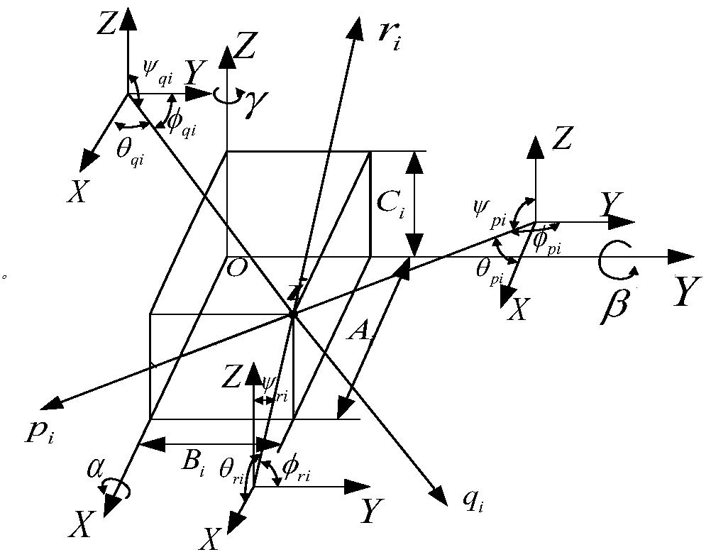
[0059] Build as figure 1 The general layout space of the engine suspension system is shown, in which point i is the i-th suspension installation point, O is the common center of mass of the powertrain, and OXYZ is the reference coordinate system taken by the research object in this article, and the common center of mass is parallel Pointing forward in the direction of the engine crankshaft is the X direction, pointing to the left of the engine is the Y direction, and vertically upward is the Z direction. α, β, γ are the rotation angles of the suspension system around the OX axis (roll), OY axis (pitch), and OZ axis (yaw) in the reference coordinate system (take the direction of the vector arrow as positive). A i , B i , C i It is an arbitrary (i-th in the figure) position suspended in the reference coordinate system, and the direction ...


PUM


Abstract

The invention discloses an engine suspension system optimization design method capable of considering the dynamic change of rigidity and damping due to excitation force. The method comprises the following steps: firstly, establishing a dynamics model of an engine suspension system; selecting a sample point in an interval formed by a suspension vertical static rigidity design range and an excitation frequency change range, calculating a dynamic rigidity and damping value corresponding to the sample point, carrying out data fitting, and establishing a prediction model; then, according to a multi-degree-of-freedom vibration theory, obtaining a vibration differential equation of the suspension system; solving the differential equation to obtain the inherent frequency of a six degrees of freedom of the suspension system and corresponding dynamic response, taking an integral sum of vibration transmissibility in a vertical direction on the centroid within a vibration frequency range as an optimization target, selecting four suspension vertical static rigidity values as optimization design variables, and taking the inherent frequency of the six degrees of freedom of the suspension system as a constraint condition; adopting a genetic algorithm to carry out optimization; and finally, verifying the feasibility of the method through a specific example. The engine suspension system optimization design method has integrity and practicality.

Description

Technical field [0001] The invention belongs to the field of automobile structure optimization, and relates to an optimization method of an engine suspension system. Background technique [0002] The engine is one of the main vibration sources of vehicles. Due to the cyclic nature of the internal combustion engine and the reciprocation of the motion mechanism, the vibration of the engine is inevitable. With the continuous improvement of the road surface and the further improvement of other assemblies, the vibration problem of the engine has become more and more prominent, which makes the vibration isolation design of the engine particularly important. In order to reduce the transmission of engine vibration to the human body, an engine suspension system appeared. For the engine, its six natural modes are coupled in multiple degrees of freedom, which expands the frequency range of resonance, making the response direction of vibration no longer single, which is not conducive to vib...

Claims


Application Information

Patent Timeline
Patent Type & Authority Patents(China)
IPC IPC(8): G06F17/50B62D65/00
Inventor 姜潮赵旭光冯恩升韩旭
Owner HUNAN UNIV
Why Eureka
Try Eureka