Deep-sea observing buoy system based on inductive coupling and satellite communication techniques

A satellite communication and inductive coupling technology, applied in the marine field, can solve the problem of sensors that can only measure a few and the water depth is within 10 meters, and can only be deployed in the offshore, and can only be deployed at a water depth of tens of meters or hundreds of meters. Location etc.

Active Publication Date: 2014-05-07
THE FIRST INST OF OCEANOGRAPHY SOA
View PDF6 Cites 33 Cited by
  • Summary
  • Abstract
  • Description
  • Claims
  • Application Information

AI Technical Summary

Problems solved by technology

However, it is difficult for most buoys to measure underwater ocean parameters in large quantities and at large depths in real time. At the same time, limited by the communication network, they can only be deployed in offshore waters.
For example, some buoys use self-contained sensors installed in the mooring subsystem of the buoy, and the data can only be read from the sensor after the buoy is recovered; the data acquisition control satellite communicator of some buoys is directly connected to each sensor cable, real-time For data transmission, but limited by the number and depth, generally only a few sensors with a water depth of 10 meters can be measured; some buoys can only be placed at a water depth of tens of meters or hundreds of meters; some buoys can only It can be deployed in the offshore, using the GPRS ground communication network or the data station with a relatively short communication distance

Method used


Image

  • Deep-sea observing buoy system based on inductive coupling and satellite communication techniques
  • Deep-sea observing buoy system based on inductive coupling and satellite communication techniques
  • Deep-sea observing buoy system based on inductive coupling and satellite communication techniques

Examples


Embodiment Construction

[0061] Attached below Figure 1-20 A deep-sea observation buoy system based on inductive coupling and satellite communication technology of the present invention will be described in detail below.

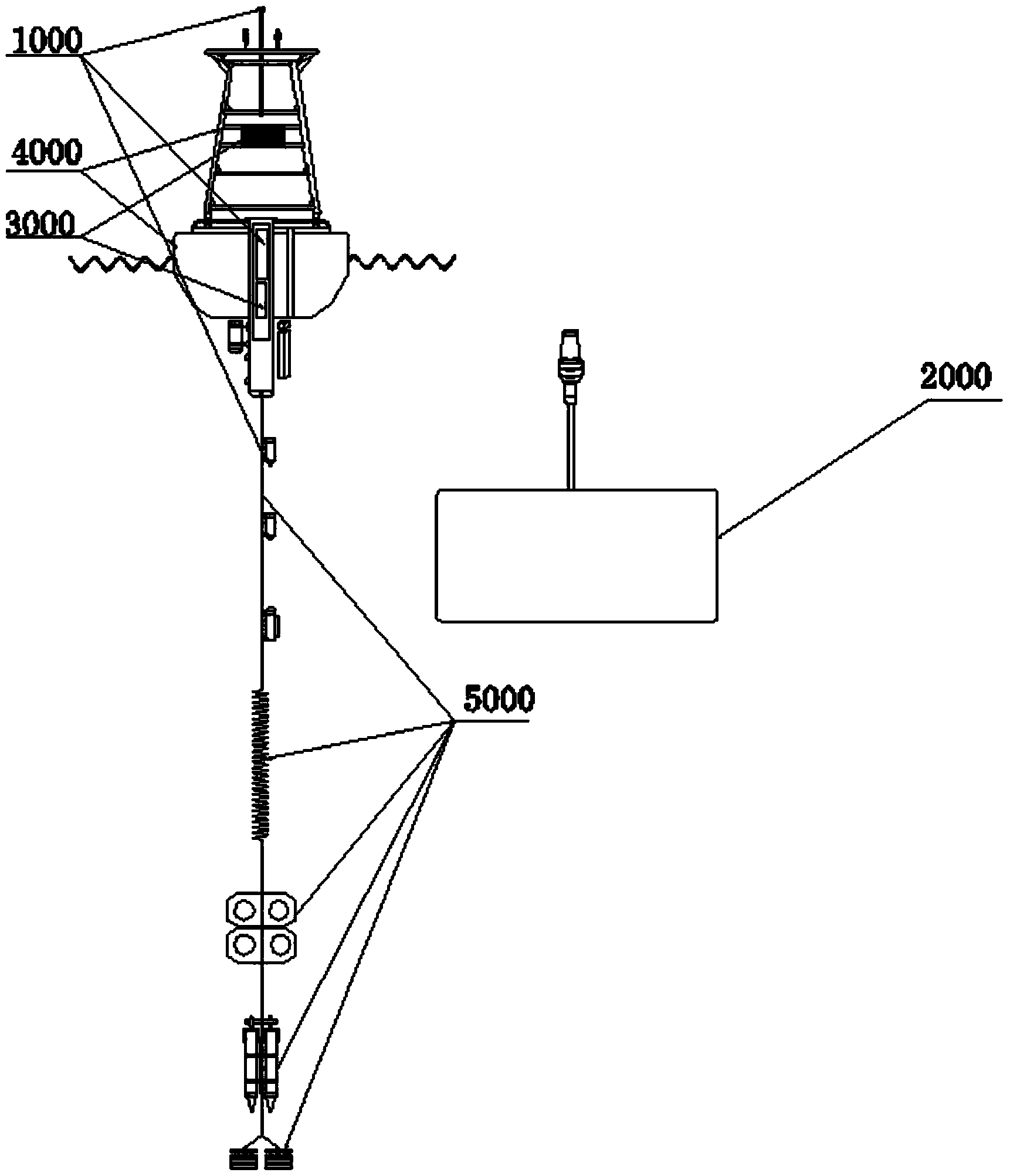
[0062] Such as figure 1 As shown, a deep-sea observation buoy system based on inductive coupling and satellite communication technology of the present invention includes a data acquisition and control satellite communication subsystem 1000, a shore station satellite communication subsystem 2000, a power supply subsystem 3000, a buoy body subsystem 4000 and The mooring subsystem 5000 is composed of five subsystems, among which the data acquisition and control satellite communication subsystem 1000, the power supply subsystem 3000, the buoy body subsystem 4000 and the mooring subsystem 5000 are assembled into a whole and deployed in deep sea areas , the shore station satellite communication subsystem 2000 is assembled into a whole and installed in the user data receiving center. Th...


PUM


Abstract

The invention provides a deep-sea observing buoy system based on inductive coupling and satellite communication techniques and belongs to the technical field of an ocean buoy platform. The deep-sea observing buoy system comprises a data collecting control satellite communication subsystem, a shore-station satellite communication subsystem, a power supply subsystem, a buoy subsystem and a mooring subsystem. A principle of a transformer is adopted by the deep-sea observing buoy system; an underwater plastic coated steel cable is taken as an iron core of the transformer, an inductive coupling connector is taken as a primary coil, the coils in various data sensors under the water are taken as secondary coils, an inductive coupling module is taken as a modulator-demodulator, and a half-duplex communication mode is established by a data-acquiring control satellite communicator in a broadcast mode through various sensors under the water, so that the real-time collection for underwater data is realized. Meanwhile, a mature satellite communication system is selected, a dial-up service supplied by the satellite communication system is utilized to establish a real-time, large-data-volume and stable communication link between a deep-sea buoy and a user data center, and the real-time transmission for deep-sea observed data is realized.

Description

(1) Technical field [0001] The invention relates to a marine technology, in particular to a deep-sea observation buoy system based on inductive coupling and satellite communication technology. (2) Background technology [0002] As a kind of ocean observation platform, buoys are playing an increasingly important role, and their application range is becoming wider and wider. However, it is difficult for most buoys to measure underwater ocean parameters in large quantities and at large depths in real time. At the same time, they can only be deployed offshore due to the limitation of communication networks. For example, some buoys use self-contained sensors installed in the mooring subsystem of the buoy, and the data can only be read from the sensor after the buoy is recovered; the data acquisition control satellite communicator of some buoys is directly connected to each sensor cable, real-time For data transmission, but limited by the number and depth, generally only a few se...

Claims


Application Information

Patent Timeline
Patent Type & Authority Applications(China)
IPC IPC(8): B63B22/00H04B7/185
Inventor 宁春林于卫东吴伟王海员王辉武刘建军刘延亮高立宝李奎平杨洋李劳钰
Owner THE FIRST INST OF OCEANOGRAPHY SOA
Why Eureka
Try Eureka