Spray-rolling type loose fiber washing machine

A technology of loose fiber and water washing machine, which is applied in the direction of removing liquid/gas/vapor with squeeze rollers, spraying/jetting textile materials, processing textile material carriers, etc. The problem of high washing cost is to ensure continuity and stability, high washing efficiency, and stable transmission process.

Active Publication Date: 2014-05-07
SHAOXING JINYU TEXITLE NEW TECH CO LTD
View PDF7 Cites 9 Cited by
  • Summary
  • Abstract
  • Description
  • Claims
  • Application Information

AI Technical Summary

Problems solved by technology

[0002] Bulk fibers are usually dyed by dyeing vats. The bulk fibers to be dyed are put into dyeing cages, hung into the dyeing vats, and the temperature and time are controlled for dyeing treatment. The cleaning process needs to consume a lot of water, cleaning agent, etc., and the cleaning cost is relatively high; while the conventional water washing machine is mainly composed of a bathing pool and several pairs of upper and lower rollers arranged up and down, and the lower roller is located in the bathing pool. In the lot

Method used


Image

  • Spray-rolling type loose fiber washing machine
  • Spray-rolling type loose fiber washing machine
  • Spray-rolling type loose fiber washing machine

Examples


Example Embodiment

[0021] Example 1

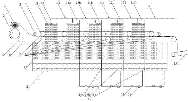
[0022] In this example, combined with figure 1 , comprising a cotton delivery roller 2, a conveying part and a spraying part, the cotton conveying roller 2 is located in front of the conveying part, and the spraying part is positioned above the conveying part, wherein,

[0023] The transmission part is made of upper guide belt 5, lower guide belt 6, upper roll 7, lower roll 8, a pair of upper driving rollers 3 and a pair of lower driving rolls 4, and the upper guide belt 5 and the lower guide belt 6 form the guide of the transmission part. Belt structure, the upper guide belt 5 and the lower guide belt 6 are provided with leakage holes 19, the diameter of the leakage holes 19 is 2-3mm, the opening rate is 50-70%, the upper roll 7 and the lower roll 8 constitute the rolls of the transmission parts Structure, a pair of upper driving rollers 3 (divided into the former driving roller and the latter driving roller according to the position) and a pair of lower d...

Example Embodiment

[0027] Example 2

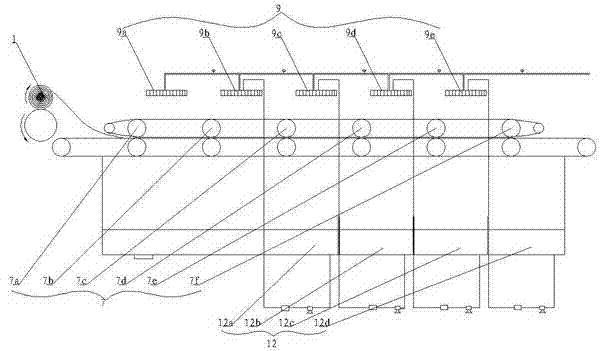
[0028] In this embodiment, a liquid collecting tank 12, a return pipe, a water pump 16 and a heat exchanger 17 are arranged below the conveying part. 17 are all installed on the return pipe, the water pump 16 draws the liquid in the liquid collection tank 12 into the spraying part for reuse, and the heat exchanger adjusts the reused liquid to a suitable temperature for use; figure 2 , three partitions 15 are arranged in the sump 12, respectively partition one 15a, partition two 15b and partition three 15c, the purpose is to divide the sump 12 into several tank areas, based on the washing effect and the recycling effect Considering comprehensively, the first partition plate 15a is set at the liquid collection tank corresponding to the bottom of the upper roll three 7c and the upper roll four 7d, and the second partition plate 15b is set at the corresponding liquid collection below the upper roll four 7d and the upper roll five 7e At the tank, the partition ...

Example Embodiment

[0030] Embodiment 3: comparative example

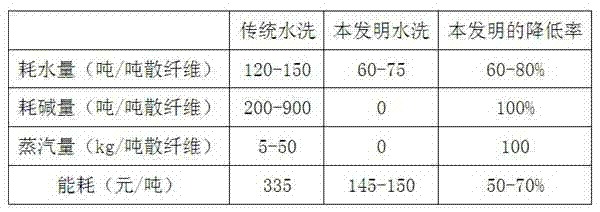
[0031] Conventional cleaning of loose fibers requires multi-channel washing, soaping and hot water washing. The loose fibers are placed in the washing tank for soaking and cleaning. During the cleaning process, an additional heat source is required for heating. At the same time, a certain amount of soaping agent etc.


PUM

PropertyMeasurementUnit
Apertureaaaaaaaaaa

Abstract

The invention relates to a spray-rolling type loose fiber washing machine, and belongs to the technical field of loose fiber dyeing. The spray-rolling type loose fiber washing machine comprises a cotton conveying roller, a transmission component and a spraying component. The cotton conveying roller is arranged in front of the transmission component, the transmission component is composed of a guide belt, a roller and a drive roller, the guide belt is horizontally arranged, and the drive roller drives the guide belt to move synchronously with the cotton conveying roller. The spraying component is located above the guide belt and used for washing the loose fibers below the spraying component, and the roller is matched with the guide belt to be mounted and used for squeezing the loose fibers which are conveyed to the guide belt through the cotton conveying roller. The spray-rolling type loose fiber washing machine is used for a loose fiber washing process, and has the advantages of being even in dyeing, small in water consumption, simple in process, and the like.

Description

technical field [0001] The invention relates to a rolling type loose fiber washing machine, which belongs to the technical field of loose fiber dehydration. Background technique [0002] Bulk fibers are usually dyed by dyeing vats. The bulk fibers to be dyed are put into dyeing cages, hung into the dyeing vats, and the temperature and time are controlled for dyeing treatment. The cleaning process needs to consume a lot of water, cleaning agent, etc., and the cleaning cost is relatively high; while the conventional water washing machine is mainly composed of a bathing pool and several pairs of upper and lower rollers arranged up and down, and the lower roller is located in the bathing pool. In the lotion, based on the structure of the washing machine, only the fabric or cloth can be washed, and the loose fiber is in a discontinuous state, so it cannot be washed with the existing washing machine. The dyed loose fiber can only be woven into fabric or After forming the net, the...

Claims


Application Information

Patent Timeline
IPC IPC(8): D06B1/02D06B23/04D06B15/02D06B23/20
Inventor 金国周程卫郦苗华马国强沈苗根杨华峰
Owner SHAOXING JINYU TEXITLE NEW TECH CO LTD
Why Eureka
Try Eureka