Chain-cylindrical lifting device

A lifting device and chain technology, applied in water conservancy projects, artificial islands, underwater structures, etc., to achieve the effect of easy operation, simple structure and high reliability

Inactive Publication Date: 2014-05-07
CHINA UNIV OF PETROLEUM (EAST CHINA)
View PDF0 Cites 0 Cited by
  • Summary
  • Abstract
  • Description
  • Claims
  • Application Information

AI Technical Summary

Problems solved by technology

[0004] The present invention aims at overcoming the defect of the existing lifting device adopting the manufacturing and maintenance cost...

Method used


Image

  • Chain-cylindrical lifting device

Examples


Embodiment Construction

[0010] Below in conjunction with accompanying drawing and example the present invention will be further described:

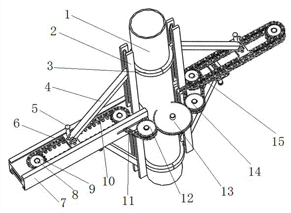
[0011] Such as figure 1 As shown, the chain-cylindrical lifting device is characterized in that it includes a pile leg 1, a guide rail plate 2, an axial displacement slider 3, a connecting plate 4, a locking pin 5, a radial translation slider 6, and a radial commutation frame 7. Power connection shaft 8, reciprocating sprocket 9, reciprocating chain 10, power chain 11, power sprocket 12, power driving gear 13, power driven wheel 14, power input sprocket 15. The axial displacement slider 3 interacts with the pile leg 1 and is connected with the connecting plate 4. The radial translation slider 6 is connected with the connecting plate 4 and is installed in the radial commutator frame 7. The reciprocating chain 10 interacts, and the reciprocating sprocket 9 is installed on the radial commutation frame 7 through the power connection shaft 8, and drives the reciproc...


PUM


Abstract

The invention relates to a hoisting device of a self-elevating drilling platform which is mainly applied to a hoisting mechanism adopting cylindrical pile legs. Reciprocating motion is achieved through motion of a chain. In the actual offshore drilling process, hoisting devices of self-elevating drilling platforms can be divided into two broad categories; cylindrical steel pipes are adopted as the pile legs, a hydraulic mechanism is used, but manufacturing and maintenance cost will be increased by adopting hydraulic equipment and the requirement for operation precision is very high, and therefore a chain-cylindrical mechanical lifting device is designed; manufacturing and maintenance cost will be reduced by replacing the hydraulic mechanism with the mechanical mechanism, the requirement for operation precision is lowered to a certain extent, and the mechanical mechanism is simple in structure, easy to operate and high in reliability.

Description

technical field [0001] The invention relates to a lifting device of a self-elevating drilling platform, in particular to a chain-barrel lifting device. Background technique [0002] The lifting transmission device is the core equipment of the jack-up drilling platform, and it is also a large-scale complete set of equipment, which is expensive and maintains. They are interrelated with the racks of the legs, the pile frame, and even the whole software. The operating and bearing conditions are special and complicated, and it can be said that they affect the whole body. [0003] At present, in the actual offshore drilling process, the lifting devices of the jack-up drilling platform are divided into two categories. Among them, cylindrical steel pipes are used as pile legs and hydraulic mechanisms are used. However, the use of hydraulic equipment will increase the cost of manufacturing and maintenance. And the precision of the operation is also very high. Contents of the inven...

Claims


Application Information

Patent Timeline
IPC IPC(8): E02B17/08
Inventor 沈祺
Owner CHINA UNIV OF PETROLEUM (EAST CHINA)
Why Eureka
Try Eureka