Heat flow balance internal combustion engine waste heat utilization system

A heat flow balance, internal combustion engine technology, applied to internal combustion piston engines, combustion engines, mechanical equipment, etc., can solve the problem of limited utilization of waste heat and achieve the effect of improving utilization

Active Publication Date: 2016-06-01
菏泽市汇信知识产权运营有限公司
View PDF3 Cites 0 Cited by
  • Summary
  • Abstract
  • Description
  • Claims
  • Application Information

AI Technical Summary

Problems solved by technology

[0002] The utilization of waste heat of internal combustion engines is of great significance for improving the overall efficiency of internal combustion engines. There are endless researches and inventions on the utilization of waste heat of internal combustion engines. So far, the exhaust heat system of the internal combustion engine has not been able to scientifically solve the unified utilization of the waste heat of the exhaust gas and the waste heat of the cooling system, so the utilization rate of the waste heat is limited

Method used


Image

  • Heat flow balance internal combustion engine waste heat utilization system
  • Heat flow balance internal combustion engine waste heat utilization system
  • Heat flow balance internal combustion engine waste heat utilization system

Examples


Embodiment 1

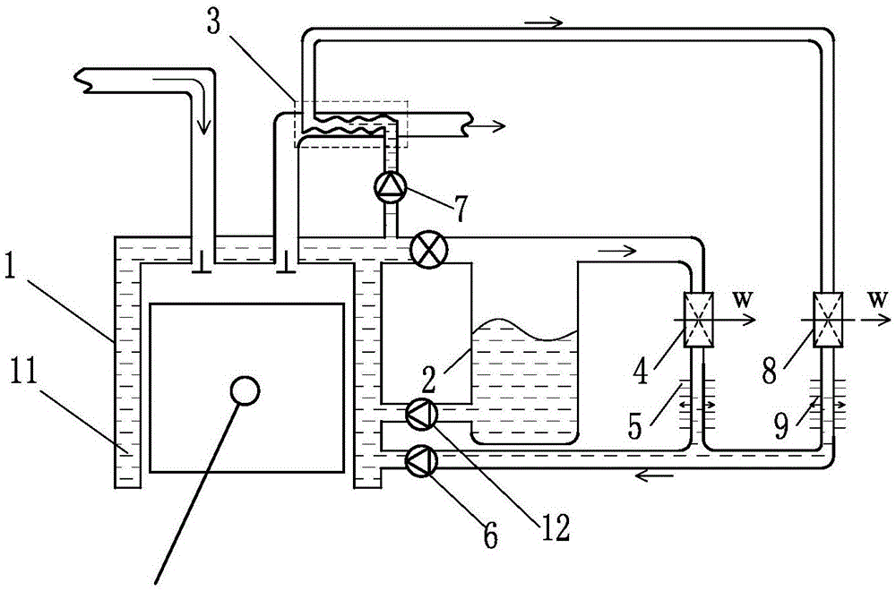
[0050] Such as figure 1 The shown heat flow balance internal combustion engine waste heat utilization system includes an internal combustion engine 1, a gas-liquid separator 2 and an exhaust heat exchanger 3, and the liquid outlet of the gas-liquid separator 2 is connected to the cooling fluid channel of the internal combustion engine 1 through a circulation pump 12 The fluid inlet of the cooling fluid channel 11 is connected, the fluid outlet of the cooling fluid channel 11 is connected with the fluid inlet of the gas-liquid separator 2, and the gas outlet of the gas-liquid separator 2 is connected with the working medium inlet of the cylinder liner steam working mechanism 4 , the working medium outlet of the liner steam working mechanism 4 communicates with the gas inlet of the liner steam condenser 5, and the liquid outlet of the liner steam condenser 5 communicates with the cooling fluid channel 11 through the liner liquid circulation pump 6 The fluid inlet of the cooling...

Embodiment 2

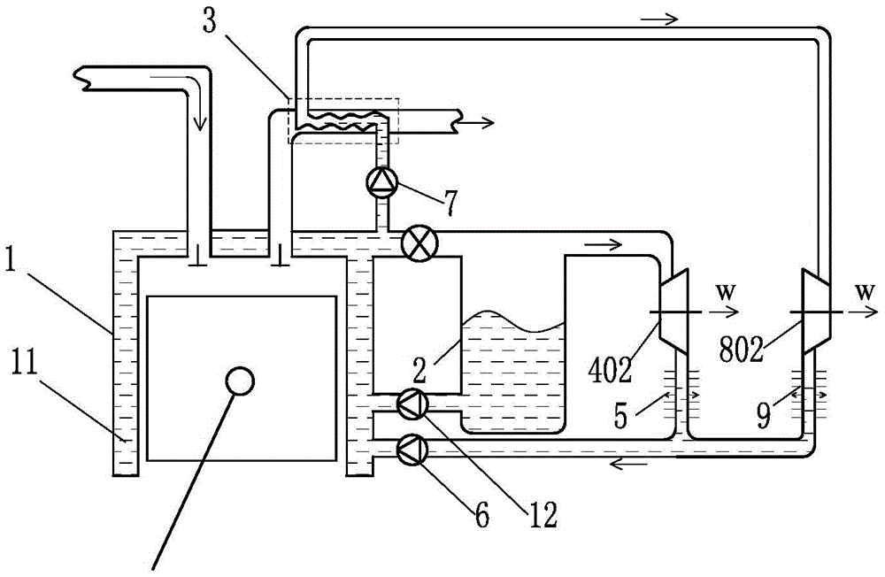
[0052] Such as figure 2 The heat flow balance internal combustion engine waste heat utilization system shown differs from Embodiment 1 in that: the cylinder liner steam work mechanism 4 is set as an impeller-type work mechanism 402, and the exhaust steam work mechanism 8 is set as an impeller-type work mechanism Mechanism 802, specifically, both the impeller-type work mechanism 402 and the impeller-type work mechanism 802 can be set as radial flow turbines.

[0053] Optionally, both the impeller type working mechanism 402 and the impeller type working mechanism 802 are set as axial flow turbines or one of them is set as a radial flow turbine and the other is set as an axial flow turbine.

Embodiment 3

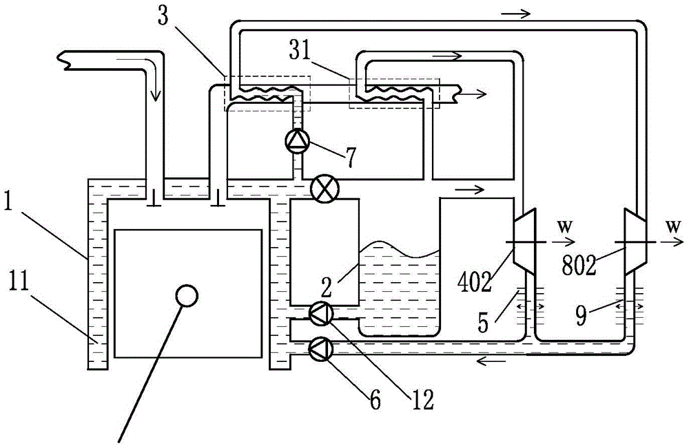
[0055] Such as image 3 The heat flow balance internal combustion engine waste heat utilization system shown differs from Embodiment 2 in that: the heat flow balance internal combustion engine waste heat utilization system also includes an auxiliary exhaust heat exchanger 31, and the gas outlet of the gas-liquid separator 2 passes through the The heated fluid channel of the auxiliary exhaust heat exchanger 31 communicates with the working medium inlet of the cylinder liner steam working mechanism 4 .

[0056] Optionally, the cylinder liner steam working mechanism 4 is changed to the cylinder liner nozzle propelling rotor working mechanism 401 , and the exhaust steam working mechanism 8 is changed to the exhaust nozzle propelling rotor working mechanism 801 .

[0057] Optionally, the cylinder liner steam work mechanism 4 is changed to the cylinder liner nozzle propulsion rotor work mechanism 401, and the exhaust steam work mechanism 8 is changed to the exhaust nozzle propulsion...


PUM


Abstract

The invention relates to the field of heat energy and power, in particular to a heat flow balance internal combustion engine waste heat utilization system. The present invention includes an internal combustion engine, a gas-liquid separator and an exhaust heat exchanger, the gas outlet of the gas-liquid separator communicates with the working fluid inlet of the steam working mechanism of the cylinder liner, and the heated fluid channel outlet of the exhaust heat exchanger It is connected with the working medium inlet of the exhaust steam working mechanism, and the working medium outlet of the exhaust steam working mechanism is connected with the liquid inlet of the cylinder liner liquid circulation pump through the exhaust steam condenser, and the exhaust steam working mechanism is connected to the outside Outputting power, the steam work mechanism of the cylinder liner outputs power to the outside. The invention can realize unified utilization of the waste heat of the exhaust gas in the waste heat of the internal combustion engine and the waste heat of the cooling system, and improves the utilization rate of the waste heat of the internal combustion engine.

Description

technical field [0001] The invention relates to the field of thermal energy and power, in particular to a waste heat utilization system of an internal combustion engine. Background technique [0002] The utilization of waste heat of internal combustion engines is of great significance for improving the overall efficiency of internal combustion engines. There are endless researches and inventions on the utilization of waste heat of internal combustion engines. So far, the exhaust heat system of the internal combustion engine has not been able to scientifically solve the unified utilization of the waste heat of the exhaust gas and the waste heat of the cooling system, so the utilization rate of the waste heat is limited. Therefore, need to invent a kind of novel internal combustion engine waste heat utilization system. Contents of the invention [0003] In order to solve the above problems, the technical scheme proposed by the present invention is as follows: [0004] Solu...

Claims


Application Information

Patent Timeline
Patent Type & Authority Patents(China)
IPC IPC(8): F02B41/02
CPCY02T10/12
Inventor 靳北彪
Owner 菏泽市汇信知识产权运营有限公司
Why Eureka
Try Eureka