Turbofan flow sensor

A flow sensor, turbofan technology, applied in the direction of volume/mass flow generated by mechanical effects, dynamic effects by detecting fluid flow, etc., can solve problems such as limited equipment or site pipeline space, restricted flow accurate measurement, etc., to ensure Effects of repeatability and consistency, stable coefficient of friction and wear resistance

Inactive Publication Date: 2014-05-07
CHINA NORTH VEHICLE RES INST
View PDF8 Cites 4 Cited by
  • Summary
  • Abstract
  • Description
  • Claims
  • Application Information

AI Technical Summary

Problems solved by technology

[0004] The purpose of the present invention is to solve the problem that in the existing flow measurement technology, due to the limited space of the equipment or the site pipeline, it is impossible to provide a long enough straight pipe section for the conventional flow sensor, which limits the accurate measurement of the flow, and provides a simple structure, volume Flow sensors that are small and do not require straight runs at both ends

Method used


Image

  • Turbofan flow sensor
  • Turbofan flow sensor

Examples


Embodiment Construction

[0014] In order to make the purpose, content, and advantages of the present invention clearer, the specific implementation manners of the present invention will be further described in detail below in conjunction with the accompanying drawings and embodiments.

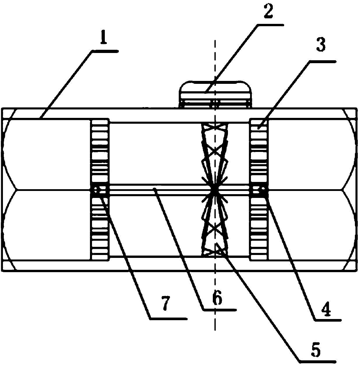
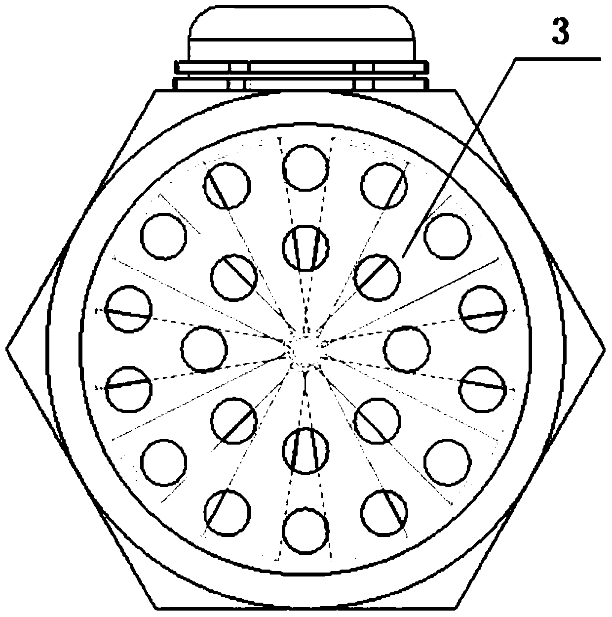
[0015] Such as figure 1 As shown, the present invention provides a turbofan flow sensor, including: a housing 1, a Hall switch 2, a turbofan frame 3, a steel ball 4, a turbofan 5, a shaft 6 and a bearing 7, and the housing 1 is The shape of a cylinder with two ends open, one end is used as a liquid inlet, and the other end is used as a liquid outlet, and the casing 1 is made of metal material, the vortex fan 5 is made of magnetic material, and the vortex fan frame 3 (as a rectifying plate) There are a plurality of through holes distributed on it, the Hall switch 2 is installed on the housing 1, and the Hall switch 2 is located directly above the turbofan 5, the turbofan frame 3, steel ball 4, turbofan 5. The shaft 6 a...


PUM


Abstract

The invention relates to a turbofan flow sensor and belongs to the technical field of flow measuring devices. The turbofan flow sensor comprises a casing (1), a Hall-effect switch (2), a turbofan rack (3), a steel ball (4), a turbofan (5), a shaft lever (6) and a bearing (7). According to the invention, the flow sensor which is designed by adopting the turbofan is determined to have a relatively stable friction coefficient and abrasive resistance at different angles within a range of 360 degrees due to the design of the structure and the parameters, and the flow measuring repeatability and consistency are ensured.

Description

technical field [0001] The invention belongs to the technical field of flow measurement devices, and in particular relates to a turbofan flow sensor. Background technique [0002] Impeller flowmeters mainly include turbine flowmeters, split rotor flowmeters, and water meters. However, the instruments are greatly affected by the distortion of the incoming flow velocity distribution and swirling flow. The upstream and downstream of the sensor require a long straight pipe section, which limits the space constraints The accuracy of the lower flow measurement, such as the application of measuring the cooling pipeline flow in the real vehicle state. Contents of the invention [0003] (1) Technical problems to be solved [0004] The purpose of the present invention is to solve the problem that in the existing flow measurement technology, due to the limited space of the equipment or the site pipeline, it is impossible to provide a long enough straight pipe section for the convent...

Claims


Application Information

Patent Timeline
Patent Type & Authority Applications(China)
IPC IPC(8): G01F1/28
Inventor 邓高寿王宇燕高振涛李培京康忠王剑李振平胡伟
Owner CHINA NORTH VEHICLE RES INST
Why Eureka
Try Eureka