
Pulse Condition Acquisition Apparatus And Method

a condition acquisition and pulse technology, applied in the field of pulse condition acquisition apparatus and method, can solve the problems of harm to people, inability to find the optimal measuring position accurately, and inability to achieve the information collection position repeatedly, so as to ensure the accuracy and repeatability of the collecting position, and avoid harm to people.

Inactive Publication Date: 2011-12-15
SHANGHAI DAOSHENG MEDICAL TECH
View PDF4 Cites 7 Cited by
  • Summary
  • Abstract
  • Description
  • Claims
  • Application Information

AI Technical Summary

Benefits of technology

[0013]1. collecting process for pulse signal is automatically achieved by electric machine, the number of turns the electric machine revolving determines the stroke the probe ascends or descends, which ensures the accuracy and repeatability of the collecting position.
[0015]use optocoupler to set up the limiting travel position of the lifting structure to avoid doing harm to people when procedure error occurred.

Problems solved by technology

Defects in the above-mentioned device is that it cannot find the optimal measuring position accurately, and the information collecting position cannot be repeatedly achieved.
With the development of technology, people began to use automatic pressure measuring mode, but the predetermined pressurizing mode is usually controlled by procedure or computer, and the limit protecting structures are not employed in hardware, so the sensor probe will press people's pulse all the time when program error occurs, which will cause harm to people when errors occur in the program and the sensor probe continuously presses the pulse of the patient.

Method used


Image

  • Pulse Condition Acquisition Apparatus And Method
  • Pulse Condition Acquisition Apparatus And Method
  • Pulse Condition Acquisition Apparatus And Method

Examples


Embodiment Construction

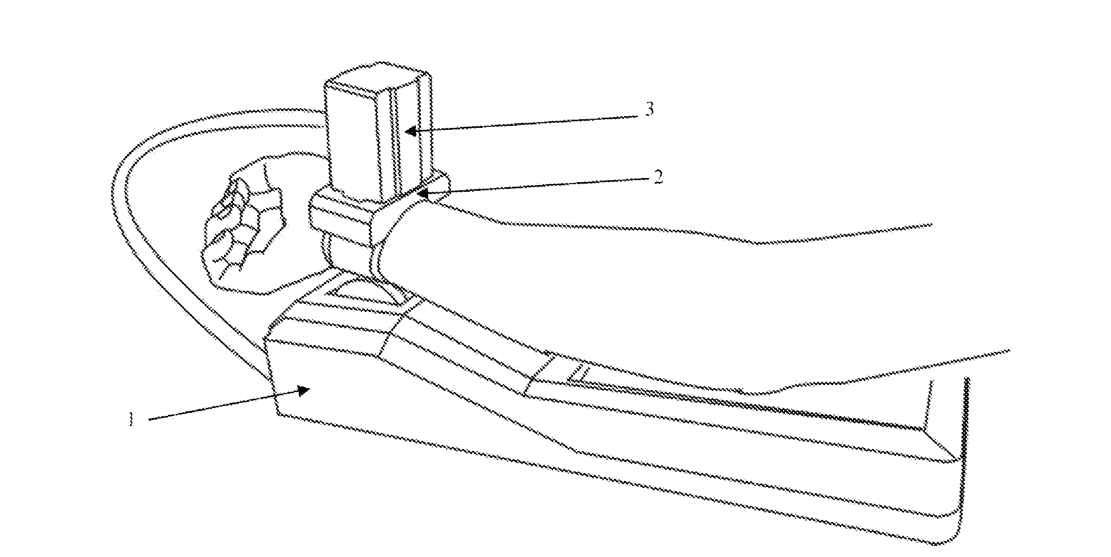
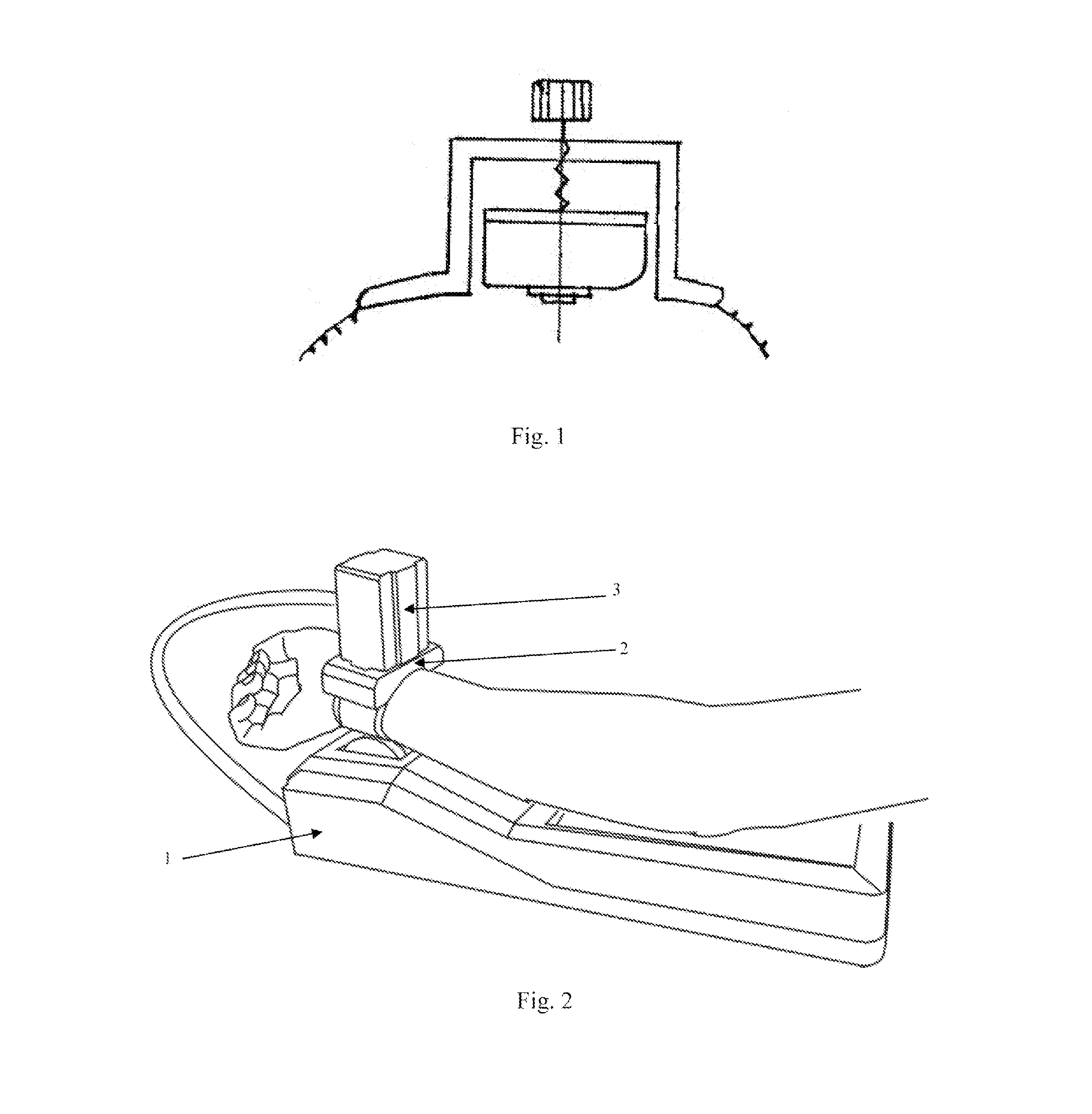
[0023]As shown in FIG. 2, it is one embodiment of the device for collecting sphygmus information in the present invention; the device comprises a base 1, a positioning component 2 and a sensor component 3. when using, the positioning component should be fixed around the wrist first and then the sensor component 3 is installed in the positioning component for detecting.

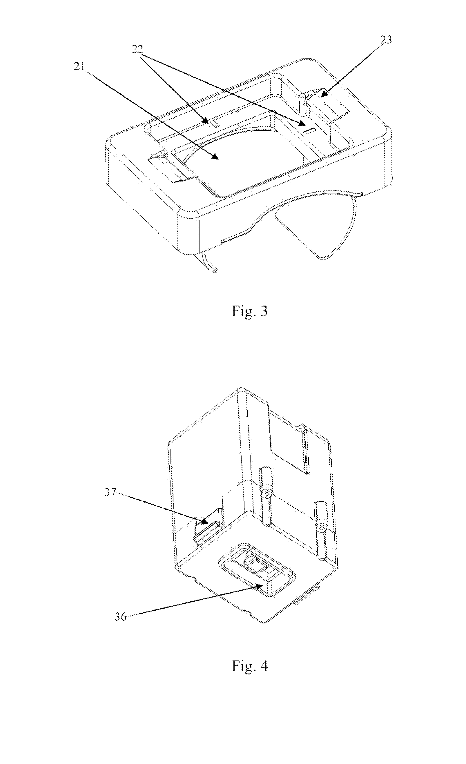
[0024]One embodiment of the sensor component in the present invention is shown in FIG. 4 and FIG. 5. FIG. 4 is the schematic diagram of the external construction; FIG. 5 is the schematic diagram of the internal construction. The sensor component 3 in the present invention includes an electric machine 31 fixed in the casing, a screw 33 fixed with said electric machine 31, a lifting structure 34 positioned outside said screw 33, and a sensor probe 35 fixed in the base of said lifting structure 34. The lifting structure 34 and the screw 33 are interconnected by screw thread. There is a guide 342 in the base of the lifting...


PUM


Abstract

A device and method for collecting sphygmus information; it includes a sensor component, said sensor component incorporates a electric machine fixed in the casing, a screw fixed with said electric machine, a lifting structure setting outside said screw, and a sensor probe fixed in the base of said lifting structure, said electric machine drives said screw to revolve when rotating, further makes said lifting structure ascended or descended relatively to said screw. The pulse signal collection can be automatically achieved, and limited protecting structure is employed in the collecting process.

Description

CROSS-REFERENCE TO RELATED APPLICATIONS [0001]The present application is a continuation of pending International patent application PCT / CN2010 / 000661 filed on May 10, 2010 which designates the United States and claims priority from Chinese patent application 200910057920.6 filed on Sep. 21, 2009, the content of which is incorporated herein by reference.FIELD OF THE INVENTION [0002]The present invention relates to a TCM diagnostic device and in particular to a device and method for collecting sphygmus information. The invention also relates to a sphygmus collecting method.BACKGROUND OF THE INVENTION [0003]The diagnostic methods the practitioner of Chinese medicine frequently used include inspection, auscultation and olfaction, interrogation and palpation, among which palpation is one of the important diagnostic methods. The practitioner of Chinese medicine feeling the pulse with fingers is to detect pulse information through tactile sensation, pressure sensation, palmesthesia recepto...

Claims


Application Information

Patent Timeline
Patent Type & Authority Applications(United States)
IPC IPC(8): A61B5/022A61B5/021
CPCA61B5/6835A61B5/02444A61B5/02A61B5/02014
Inventor DI, DANPAN, ZHEPAN, YUETANG, WEICHANG
Owner SHANGHAI DAOSHENG MEDICAL TECH
Learn More