
Long mirror installation device

An installation device and strip mirror technology, applied in the field of lithography, can solve problems such as poor flatness of the strip mirror, and achieve the effects of overcoming deformation, reducing processing difficulty and saving material consumption

Active Publication Date: 2016-02-03
SHANGHAI MICRO ELECTRONICS EQUIP (GRP) CO LTD
View PDF7 Cites 0 Cited by
  • Summary
  • Abstract
  • Description
  • Claims
  • Application Information

AI Technical Summary

Problems solved by technology

[0007] The purpose of the present invention is to provide a long strip mirror installation device to overcome the problem of poor flatness caused by the long strip mirror

Method used


Image

  • Long mirror installation device
  • Long mirror installation device
  • Long mirror installation device

Examples


Embodiment 1

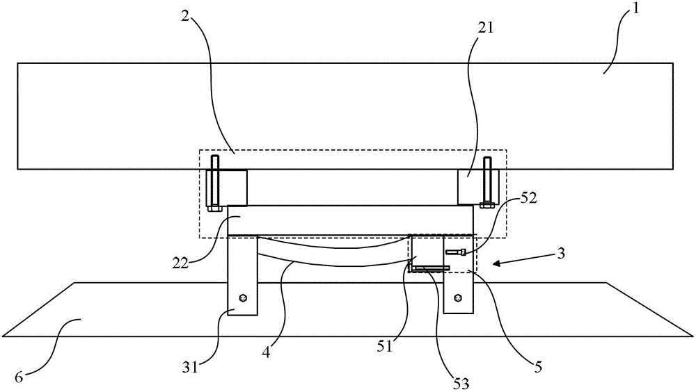
[0033] Please focus on reference figure 1 ,like figure 1 As shown, the embodiment of the present invention provides a strip mirror installation device, which is arranged on the lower surface of the main substrate 1 of the workpiece table of the lithography machine, and includes a three-degree-of-freedom level adjustment device 2, a mounting frame 3, and an elastic reed 4 and a reed deformation adjustment device 5, the three-degree-of-freedom level adjustment device 2 is arranged on the lower surface of the main substrate 1, and the installation frame 3 is arranged on the lower surface of the three-degree-of-freedom level adjustment device 2 , the installation frame 3 is used to fix the long mirror 6 , and the reed deformation adjusting device 5 can adjust the concave-convex degree of the elastic reed 4 so that it can generate different sizes of forces on the long mirror 6 .

[0034]Further, the three-degree-of-freedom level adjustment device 2 includes a three-point levelin...

Embodiment 2

[0042] The difference between the long mirror installation device provided in this embodiment and that in Embodiment 1 is that please refer to Figure 9 and Figure 10 ,like Figure 9 and Figure 10 As shown, the reed deformation adjustment device 5 includes two installation base outer sleeves 51' and two installation base inner sleeves 52', and the two installation base outer sleeves 51' are arranged at intervals along the width direction of the strip mirror 6. On the lower surface of the base 22, the distance between them is greater than the width of the strip mirror 6, and the two mounting base outer sleeves 51' are slidingly connected to the corresponding two mounting base inner sleeves 52' or through internal and external threads. connected, the two ends of the elastic reed 4 are respectively arranged on the two installation base inner sleeves 52', and the installation base inner sleeves 52' can move up and down in the installation base outer sleeve 51', thereby adjusti...


PUM

PropertyMeasurementUnit
thicknessaaaaaaaaaa
thicknessaaaaaaaaaa

Abstract

The invention provides a long mirror installation device, which is arranged on the lower surface of the main substrate of the photolithography machine workpiece table. The long mirror installation device changes the length of the long mirror by applying force to the middle section of the long mirror. In the state of stress, the difference between the minimum deformation point and the maximum deformation point of the long mirror becomes smaller, thus playing the role of correcting the flatness of the long mirror and improving the horizontal accuracy of the long mirror. The long mirror installation device There is no need for high processing precision of the long mirror, which reduces the processing difficulty of the long mirror, and does not need to increase the thickness of the long mirror to overcome the deformation caused by its own weight, which greatly saves the material consumption of the long mirror and reduces the cost , and the improvement of the horizontal accuracy of the strip mirror also improves the Z-direction measurement accuracy of the workpiece table laser interferometer.

Description

technical field [0001] The invention relates to the field of photolithography technology, in particular to a long mirror installation device. Background technique [0002] Laser interferometer is usually used to measure the Z-direction motion of the workpiece table of lithography machine. The measurement optical path is realized by the reflection of the 45-degree mirror installed on the micro-motion table and the long mirror installed on the lower surface of the main substrate. In addition, according to the optical reflection In principle, the error caused by the geometry of the working mirror surface of the strip mirror usually leads to a measurement error of 2 times, so it is very important to control the levelness of the working mirror surface of the strip mirror. [0003] The strip mirror is a kind of precision optical component, and the processing accuracy is relatively strict. The usual processing index is that the flatness in the entire light transmission range is not...

Claims


Application Information

Patent Timeline
Patent Type & Authority Patents(China)
IPC IPC(8): G02B7/02G03F7/20
Inventor 吴飞胡志宏彭巍吴萍袁志扬
Owner SHANGHAI MICRO ELECTRONICS EQUIP (GRP) CO LTD
Learn More