Device and method for automatically identifying power model of driver

An automatic identification and driver technology, applied in instruments, electrical digital data processing, etc., can solve the problems of difficult to identify the parameters of the driving part, time-consuming, errors, etc., and achieve the effect of low chip price, low cost and good scalability.

Active Publication Date: 2014-05-07
深圳市弘粤驱动有限公司
View PDF3 Cites 5 Cited by
  • Summary
  • Abstract
  • Description
  • Claims
  • Application Information

AI Technical Summary

Problems solved by technology

This manual method is cumbersome, time-consuming, and can lead to errors due to human negligence
In addition, when a part of the inverter or servo drive fails, the control part and the drive part need to be reassembled. At this time, if the pasted barcode is lost or unclear, it is very difficult to identify the parameters of the drive part.

Method used


Image

  • Device and method for automatically identifying power model of driver
  • Device and method for automatically identifying power model of driver
  • Device and method for automatically identifying power model of driver

Examples


Embodiment Construction

[0026] The present invention will be further described below in conjunction with the accompanying drawings and embodiments.

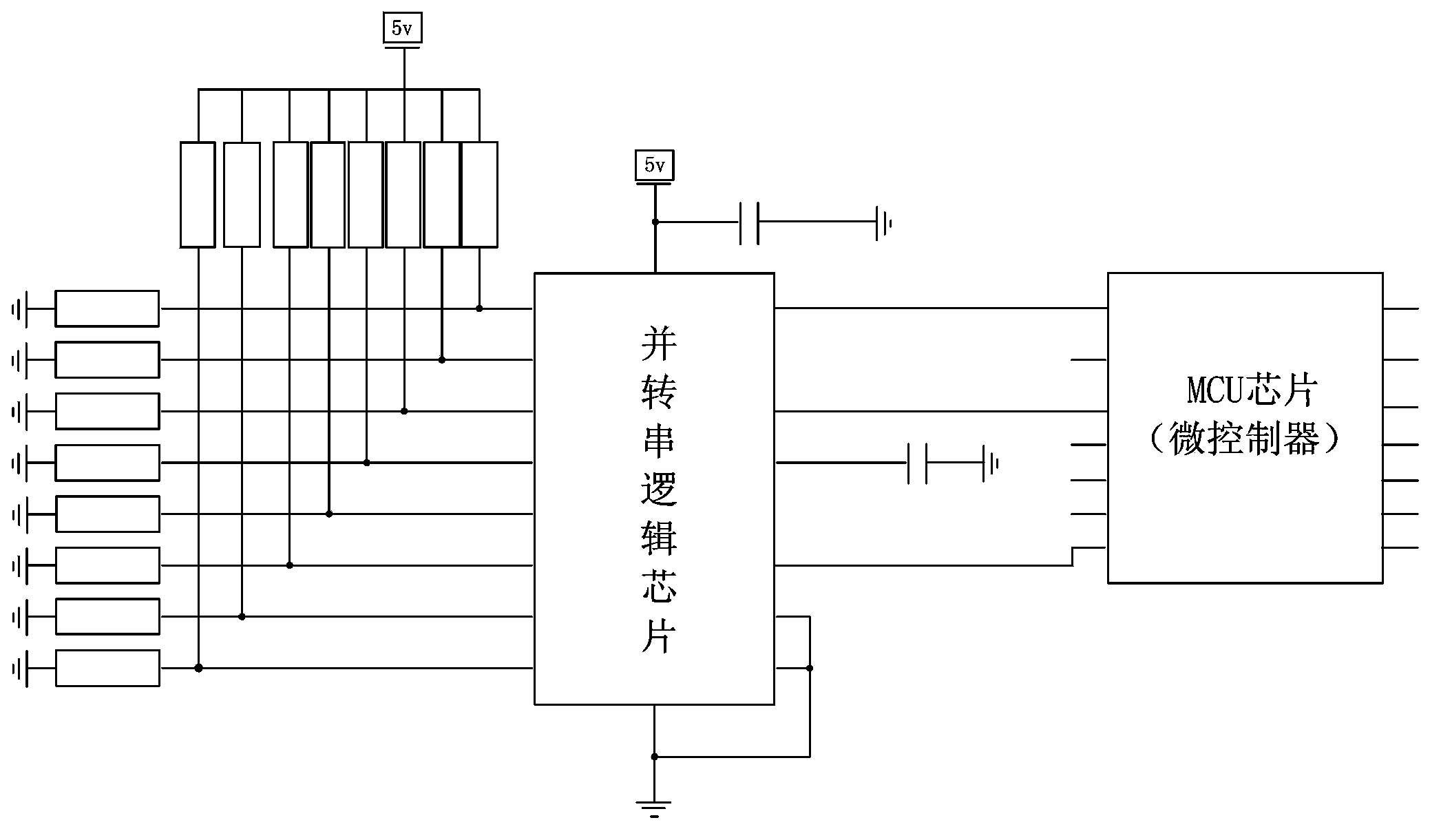
[0027] refer to figure 1 As shown, the present invention discloses a device for automatically identifying the power model of the driver, which includes

[0028] At least one parallel-to-serial logic chip, the parallel-to-serial logic chip has a parallel signal input terminal and a serial signal terminal, and the serial signal terminal includes a clock signal input terminal, a signal loading terminal and a data output terminal;

[0029] An MCU chip, the MCU chip has at least three I / O interfaces corresponding to the serial signal end, and the clock signal input end, signal loading end and data output end are respectively connected to the corresponding I / O interfaces on the MCU chip. O interface signal connection. The MCU chip can adopt the MCU chip of the control part in the driver.

[0030] Generally, the parallel-to-serial logic chip has 8 parallel ...


PUM


Abstract

The invention discloses a device and a method for automatically identifying the power model of a driver. The device comprises at least one parallel to serial logic chip and an MCU (Microprogrammed Control Unit) chip; the parallel to serial logic chip comprises the parallel signal input end and the serial signal end; the serial signal end comprises the clock signal input end, the signal loading end and the data output end; the MCU chip comprises at least three I / O (Input / Output) interfaces which are corresponding to the serial signal end; the clock signal input end, the signal loading end and the data output end are in signal connection with the corresponding I / O interfaces which are arranged on the MCU chip respectively. The method comprises step 1, arranging the high electrical level and or the low electrical level which are or is matched with the power model of the driver at the parallel signal input end of the parallel to serial logic chip; step 2, performing automatic identification on an identification code of the power model of the driver through the MCU chip; step 3, automatically arranging related parameters of the driver according to the identification code of the power model through the MCU chip. According to the device and the method for automatically identifying the power model of the driver, the power model of the driver can be automatically identified without manual intervention, the consumed time is short, and the identification is accurate.

Description

【Technical field】 [0001] The invention relates to the technical field of frequency converters and servo drives, in particular to a method for automatically identifying the power model of the drive. 【Background technique】 [0002] Inverter and servo drive are mainly composed of two parts: control and drive. Generally, frequency converters and servo drives are divided into many power models. The control part of each power model is the same, and the drive part is different. However, for the control part, it is necessary to know the accurate power, current, voltage and other parameters of the drive part when powering on, otherwise the motor cannot be driven correctly, and some protection programs cannot be run correctly. [0003] At present, basically most inverters and servo drivers know the parameters of the drive part through function code setting. Specifically, manually identify the parameters of the drive part according to the pasted barcode, and then set the correspondin...

Claims


Application Information

Patent Timeline
Patent Type & Authority Applications(China)
IPC IPC(8): G06F13/10
Inventor 李永利凡峻
Owner 深圳市弘粤驱动有限公司
Why Eureka
Try Eureka