
Method for predicting fatigue life of BGA (Ball Grid Array) welding spot under heat-vibration combined loads

A fatigue life prediction, combined load technology, applied in special data processing applications, instruments, electrical digital data processing, etc., can solve the problems of accelerated solder joint crack propagation, solder joint failure, and actual situation inconsistency.

Active Publication Date: 2014-05-07
BEIHANG UNIV
View PDF3 Cites 43 Cited by
  • Summary
  • Abstract
  • Description
  • Claims
  • Application Information

AI Technical Summary

Problems solved by technology

But there are also some disadvantages: the life of the solder joints is shorter
Especially when there is interaction between dynamic stress and thermal stress in the solder joint, it will accelerate the crack growth process in the solder joint and quickly lead to premature failure of the solder joint
Electronic products working in aviation, aerospace and military environments are often subjected to simultaneous vibration loads and thermal cycle loads. However, it is still quite difficult to estimate the life of electronic products working in a combined thermal and vibration load environment
In actual work and scientific research, engineers basically adopt the traditional linear damage accumulation method, which does not consider the impact of thermal cycle load on vibration, and calculates the thermal and vibration damage separately and accumulates them. Although this method is simple Easy to do, but not realistic

Method used


Image

  • Method for predicting fatigue life of BGA (Ball Grid Array) welding spot under heat-vibration combined loads
  • Method for predicting fatigue life of BGA (Ball Grid Array) welding spot under heat-vibration combined loads
  • Method for predicting fatigue life of BGA (Ball Grid Array) welding spot under heat-vibration combined loads

Examples


Embodiment example

[0095] Taking the solder joints of BGA packaged components of model BGA225T1.5-DC15 as an example, the application of this method is introduced, and the usability and effectiveness of the method for predicting the fatigue life of BGA solder joints under thermal shock combined load are verified.

[0096] Step 1: Use Surface Evolver software to model a single BGA solder joint, input initial condition parameters, as shown in Table 1, and establish a finite element model of this BGA solder joint.

[0097] Table 1 Initial condition parameter table

[0098] parameter name

accurate value

Solder ball additional gravity load

0.009996g

Solder ball surface tension

480erg / cm2

Solder ball density

9g / cm3

Top Pad Diameter

0.56mm

Equivalent Solder Ball Diameter

0.76mm

[0099] Step 2-Step 3: Use Ansys software to perform thermal cycle simulation on the BGA solder joint finite element model, and the temperature range ...


PUM


Abstract

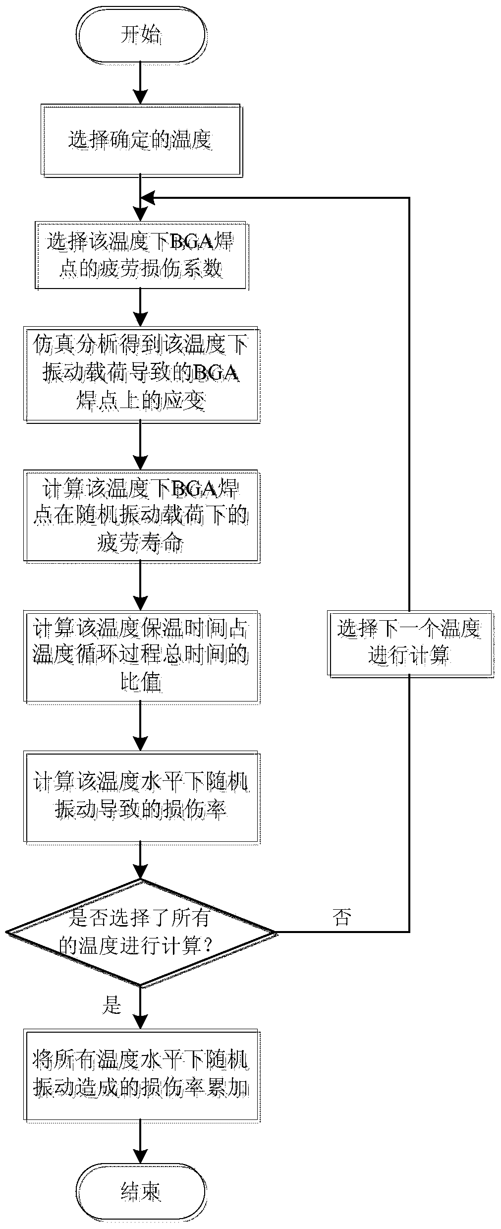
The invention provides a method for predicting the fatigue life of a BGA (Ball Grid Array) welding spot under heat-vibration combined loads, comprising the following steps of (1), establishing the finite element model of a single BGA welding spot by adopting finite element analysis software; (2), carrying out heat cycle simulation on the BGA welding spot according to the conditions of a working environment; (3), calculating the damage rate of the BGA welding spot under heat cycle loads according to the result of heat cycle simulation; (4), carrying out random vibration simulation on the BGA welding spot under various temperature conditions; (5), calculating the damage rate caused by random vibration loads, of the BGA welding spot under the influence of heat cycle loads; (6) calculating the total damage rate of the BGA welding spot under the common action of the heat cycle loads and the random vibration loads; (7), calculating and obtaining the predicted service life of the BGA welding spot under the heat-vibration combined loads. By the adoption of the method, the precision of predicting the fatigue life of the BGA welding spot under the heat-vibration combined loads in practical production can be improved, and certain project application values are provided.

Description

Technical field: [0001] The invention relates to a method for predicting the fatigue life of a Ball Grid Array (BGA) solder joint under a thermal vibration combined load. By calculating the damage rate of a BGA solder joint under a thermal vibration combined load, the thermal vibration combined load is obtained. The fatigue life of lower BGA solder joints belongs to the technical field of system engineering system reliability. Background technique: [0002] The fourth-generation packaging technology—Surface Mount Technology (SMT) is one of the top ten new technologies in the world in the 1990s, and it was soon widely used in integrated circuits, with low cost, high integration, and low weight. Lightweight and easy to automate. But there are also some disadvantages: the life of the solder joints is relatively short. This is because SMT-packaged electronic components are often subjected to stress loads in the working environment during the working process, so that the solder...

Claims


Application Information

Patent Timeline
Patent Type & Authority Applications(China)
IPC IPC(8): G06F17/50
Inventor 胡薇薇孟祥坤孙宇锋赵广燕牟浩文
Owner BEIHANG UNIV
Learn More