Eleven-level single-phase inverter
A single-phase inverter and level technology, which is applied to electrical components, AC power input to DC power output, output power conversion devices, etc., can solve the problems of large number of power switches and complex topology, and achieve power Fewer switches, simple control and stable operation
- Summary
- Abstract
- Description
- Claims
- Application Information
AI Technical Summary
Problems solved by technology
Method used
Image

Examples
Embodiment 1
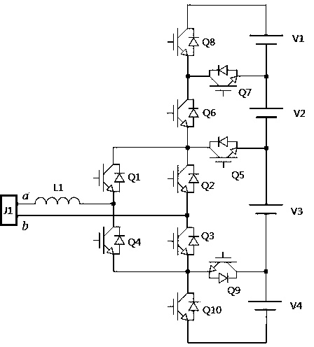
[0018] like figure 1 As shown, an eleven-level single-phase inverter includes an AC transfer port J1, a reactor L1, a power switch circuit, a DC power supply V1, a DC power supply V2, a DC power supply V3, a DC power supply V4, and a DC power supply V5, The AC transfer port J1 is provided with a terminal and a b terminal. The power switch circuit includes a power switch Q1, a power switch Q2, a power switch Q3, a power switch Q4, a power switch Q5, a power switch Q6, a power switch Q7, a power switch Q8, and a power switch. Switch Q9, power switch Q10, power switch Q11 and power switch Q12, a total of 12 power switches, one end of the reactor L1 is connected to the a terminal of the AC transfer port J1, the other end of the reactor L1 is connected to the emitter of the power switch Q1, the power switch The collector of Q4 is electrically connected, the b terminal of the AC transfer port J1 is electrically connected to the emitter of the power switch Q2, the collector of th...
Embodiment 2
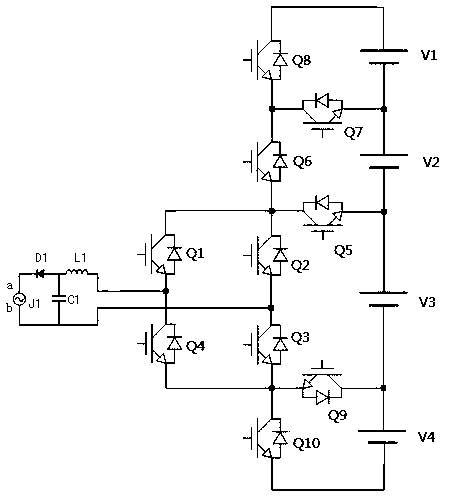
[0026] In embodiment 2, as figure 2 As shown, a diode D1 and a filter capacitor C1 are connected between the reactor L1 and the AC port J1, the anode of the diode D1 is connected to the reactor L1, the cathode of the diode D1 is connected to the terminal a of the AC adapter port, and the two ends of the filter capacitor C1 are respectively Connect the anode of diode D1 to the b end of the AC transfer port J1. The diode D1 is used to prevent the backflow of the AC grid energy and prevent the grid current from flowing to the inverter side when the bus voltage is low. The filter capacitor C1 is used for the filtering of the inverter circuit. , filter out high frequency current components. Power switch Q1, power switch Q2, power switch Q3, power switch Q4, power switch Q5, power switch Q6, power switch Q7, power switch Q8, power switch Q9, power switch Q10, power switch Q11 and power switch Q12 are all MOSFETs . Others are the same as in Example 1.
PUM
 Abstract
Description
Claims
Application Information
 - R&D
- Intellectual Property
- Life Sciences
- Materials
- Tech Scout
- Unparalleled Data Quality
- Higher Quality Content
- 60% Fewer Hallucinations
Browse by: Latest US Patents, China's latest patents, Technical Efficacy Thesaurus, Application Domain, Technology Topic, Popular Technical Reports.
© 2025 PatSnap. All rights reserved.Legal|Privacy policy|Modern Slavery Act Transparency Statement|Sitemap|About US| Contact US: help@patsnap.com