Compaction device for a spinning machine

A spinning machine and compression unit technology, which is applied in spinning machines, spinning machines with continuous winding, textiles and papermaking, etc., can solve the problem of inflexibility of the pinch roller, and achieve compact structure and compact structure unit Effect

Active Publication Date: 2014-05-07
MASCHINENFABRIK RIETER AG
View PDF6 Cites 3 Cited by
  • Summary
  • Abstract
  • Description
  • Claims
  • Application Information

AI Technical Summary

Problems solved by technology

[0005] The installation of the pinch rollers proposed here requires special tools and is inflexible

Method used


Image

  • Compaction device for a spinning machine
  • Compaction device for a spinning machine
  • Compaction device for a spinning machine

Examples


Embodiment Construction

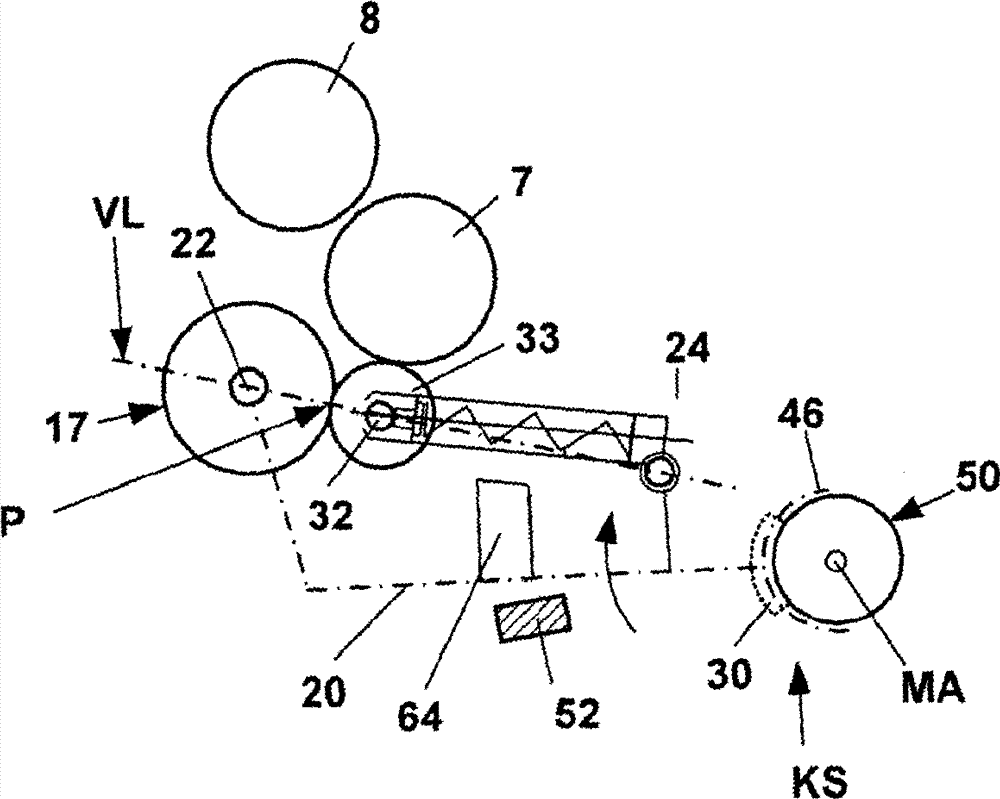
[0026] figure 1Shows a schematic side view of the spinning position 1 of a spinning machine (ring spinning machine) with a drafting unit 2 with a pair of input rollers 3, 4, a pair of intermediate rollers 5, 6 And an output roller pair 7,8. An apron 12 , 13 is each guided around the intermediate rollers 5 , 6 and is held in the position shown in each case around a cage (not shown in detail). The upper rollers 4 , 6 , 8 of the pair of rollers are designed as pressure rollers, which are rotatably mounted via axles 4 a , 6 a , 8 a on a pivotably mounted pressure rod 10 . The pressure lever 10 is mounted pivotably about an axle 15 and, as shown schematically, is loaded via a spring element F. FIG. The spring element can also be, for example, an air hose. The rollers 4 , 6 , 8 are pressed against the lower roller 3 , 5 , 7 of the roller pair via a schematically indicated spring load in order to form a clamping point for the fiber product. The roller pairs 3 , 5 , 7 (not shown) ...


PUM


Abstract

The invention relates to a compaction unit (VM) for compacting a sliver delivered from a drafting unit (2) of a spinning machine, wherein the compaction unit (VM) comprises a support (20) on which at least one suction drum (17) provided with a suction zone (Z) is rotatably mounted on an axle (22). A respective nip roll (33) mounted on the support (20) bears on the suction drum in order to form a nip line (P) at the end of the suction zone (Z). In order to improve known devices of loading arrangements for nip rolls on suction drums (17), according to the invention the nip roll (33) is rotatably mounted on an axle (32) on a pressure arm (72) that is pivotally mounted on the support (20) and is provided with a spring element (F2).

Description

technical field [0001] The invention relates to a compression unit for compressing a fiber combination delivered by a drafting unit of a spinning machine, wherein the compression unit has a support on which at least one, a suction zone ( The suction rollers (17) of Z) are rotatably supported on a wheel shaft, and in order to form a clamping line (P) at the end of the suction zone (Z), there is respectively one mounted on the support ( The pinch roller (33) on 20) is attached to the support under the action of a pressure element (F2) installed on the support. Background technique [0002] A large number of embodiments are known in practice, in which a compression device is arranged downstream for the compression of the fiber product (fibrous sliver) delivered by a stretching unit. Coupled to such a compression device, the compressed fiber product is fed to a twist generating device after passing through a clamping point. Such a twist generating device is formed, for example...

Claims


Application Information

Patent Timeline
Patent Type & Authority Applications(China)
IPC IPC(8): D01H5/72D01H1/02
CPCD01H1/025D01H5/72D01H5/74
Inventor L.马里纳R.内格里G.施内德
Owner MASCHINENFABRIK RIETER AG
Why Eureka
Try Eureka