Microalgae continuous reaping device and method

A harvesting device and technology for microalgae, applied in biochemical equipment and methods, enzymology/microbiology devices, biochemical cleaning devices, etc., to achieve the effect of simple technical principle, convenient processing, and promotion of large-scale cultivation and industrialization of microalgae

Inactive Publication Date: 2014-05-14
HUBEI UNIV OF TECH
View PDF5 Cites 2 Cited by
  • Summary
  • Abstract
  • Description
  • Claims
  • Application Information

AI Technical Summary

Problems solved by technology

[0003] At present, except microalgae with few cells (or aggregates) and large microalgae (Spirulina, Ge Xianmi) that have begun to be industrialized and put into the market, most Microalgae has been in the stage of cultivation and research and development, and it is difficult to produce on a large scale. The biggest problem is that the single-cell microalgae is small and difficult to separate from algae water cheaply.
The microalgae in the current research and development stage are mostly harvested by centrifuge centrifugation. This method consumes a lot of power and requires high equipment, and the cost of obtaining algae powder is quite high. This method must also separate the harvesting equipment from the algae photoreactor. The obtained wastewater cannot be effectively recycled, and the wastewater may cause environmental pollution, so the centrifugation method is not conducive to industrial production

Method used


Image

  • Microalgae continuous reaping device and method
  • Microalgae continuous reaping device and method

Examples


Embodiment Construction

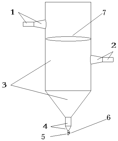
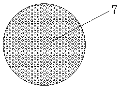
[0021] A microalgae continuous harvesting device, comprising a settling column 3, a concentration column 4 with a smaller diameter than the settling column is connected below the settling column 3, and an algae outlet pipe with a smaller diameter than the concentration column is connected below the concentration column 4 5. A valve 6 is installed on the algae outlet pipe 5; a water inlet 1 and a water outlet 2 are connected on the outer wall of the settling column 3, and the water inlet 1 is higher than the water outlet 2, and is fixed on the inner wall of the settling column 3 There is a porous energy dissipation basin 7, and the position of the energy dissipation basin 7 is between the water inlet 1 and the water outlet 2. like figure 1 shown.

[0022] The settling column 3 is composed of a settling tube and a settling transition tube. The settling tube is made of transparent organic glass with a diameter of 400 mm and a length of 1000 mm. Made of glass, the length is 20...


PUM

PropertyMeasurementUnit
diameteraaaaaaaaaa
diameteraaaaaaaaaa
lengthaaaaaaaaaa

Abstract

The invention relates to a microalgae continuous reaping device and method. The reaping device comprises a sedimentation column. The lower face of the sedimentation column is connected with a concentration column with the pipe diameter smaller than that of the sedimentation column. The lower face of the concentration column is connected with an algae-out pipe with the pipe diameter smaller than that of the concentration column. The algae-out pipe is provided with a valve. The outer wall of the sedimentation column is connected with a water inlet and a water outlet. The water inlet is higher than the water outlet. A multi-hole energy dissipation basin is fixed on the inner wall of the sedimentation column. The energy dissipation basin is placed between the water inlet and the water outlet. According to the microalgae continuous reaping device, the characteristic that algae density is larger than water body density is used, after a high-flow-speed water body with many algae passes through the device, flow speed is lowered quickly, algae bodies are subjected to sedimentation and are gathered to be discharged out of the device, after separation, the water body can flow out of the device and enter a reactor for reusing, and then the purpose of water-algae continuous separating and reaping can be achieved. The device is simple in technology principle and convenient to operate, materials are cheap, and machining is convenient.

Description

technical field [0001] The invention belongs to the technical field of microalgae cultivation, and in particular relates to a microalgae continuous harvesting device and method. Background technique [0002] Microalgae are rich in oil, and the oil content of some unicellular microalgae can exceed 50% of the dry weight. Its output per unit area is 80-100 times that of general oil-producing plants, and it is an important biomass energy that may replace fossil energy. Secondly, microalgae can absorb a large amount of pollutants such as nitrogen and phosphorus during the growth process. If the microalgae in the water body can be effectively extracted, the microalgae culture can effectively purify the sewage and produce recycled water. In addition, microalgae have fast growth, short harvest time, and high photosynthetic utilization rate, which can efficiently and quickly absorb CO in the air. 2 Generate organic matter, which has the application prospect of alleviating the glob...

Claims


Application Information

Patent Timeline
Patent Type & Authority Applications(China)
IPC IPC(8): C12M1/00C12N1/12
CPCC12M29/18C12M47/02
Inventor 杨正健刘德富卢凡万端极张佳磊纪道斌崔玉洁
Owner HUBEI UNIV OF TECH
Why Eureka
Try Eureka