Integrated ceiling structure

An integrated ceiling, instant heating technology, applied in the field of bathroom decoration, can solve problems such as the overall decoration is not beautiful, generous, water resources and electrical energy waste, installation is not humane enough, etc., to achieve overall beauty, reduce waste, and simple appearance. Effect

Active Publication Date: 2017-01-04
JIAXING GELER INTEGRATED CEILING TECH
View PDF6 Cites 3 Cited by
  • Summary
  • Abstract
  • Description
  • Claims
  • Application Information

AI Technical Summary

Problems solved by technology

[0004] Traditional instant water heaters are generally electrically connected to the power supply through wires alone, and ordinary power switch joints are used to control the on-off of instant water heaters. Although this installation structure is simple, the installation is not user-friendly. there will be inconvenience
[0005] In the existing bathroom installation structure, the ceiling panel is generally installed near the ceiling on the upper part of the bathroom, and the water heater is installed under the ceiling panel. Due to the more or less difference in the design style of the water heater and the ceiling panel, this installation method has disadvantages. Coordination, and the overall decoration is not beautiful and generous
If the bathroom space is small, in order to minimize the space occupied by the bathing device or other devices, which will affect people's normal use, the water heater will be installed in a place other than the kitchen and other bathrooms during installation. It brings certain inconvenience, and in this installation method, the distance from the outlet on the water heater to the water tap is long, and the hot water in this section of water pipe is easy to cool down. Only after the water in the section of the water pipe is discharged clean can there be hot water, which will easily cause double waste of water resources and electric energy

Method used


Image

  • Integrated ceiling structure
  • Integrated ceiling structure
  • Integrated ceiling structure

Examples


Embodiment Construction

[0037] The present invention will be further described below in conjunction with the accompanying drawings and specific embodiments.

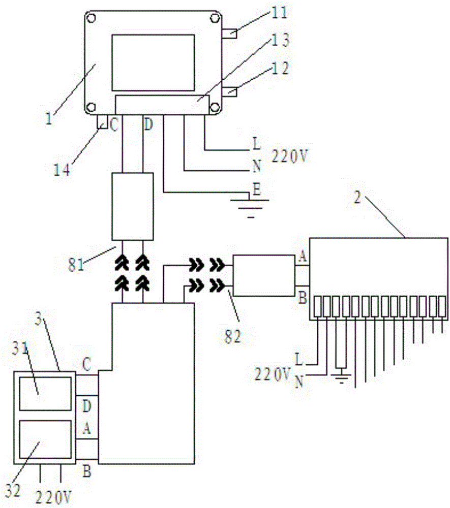
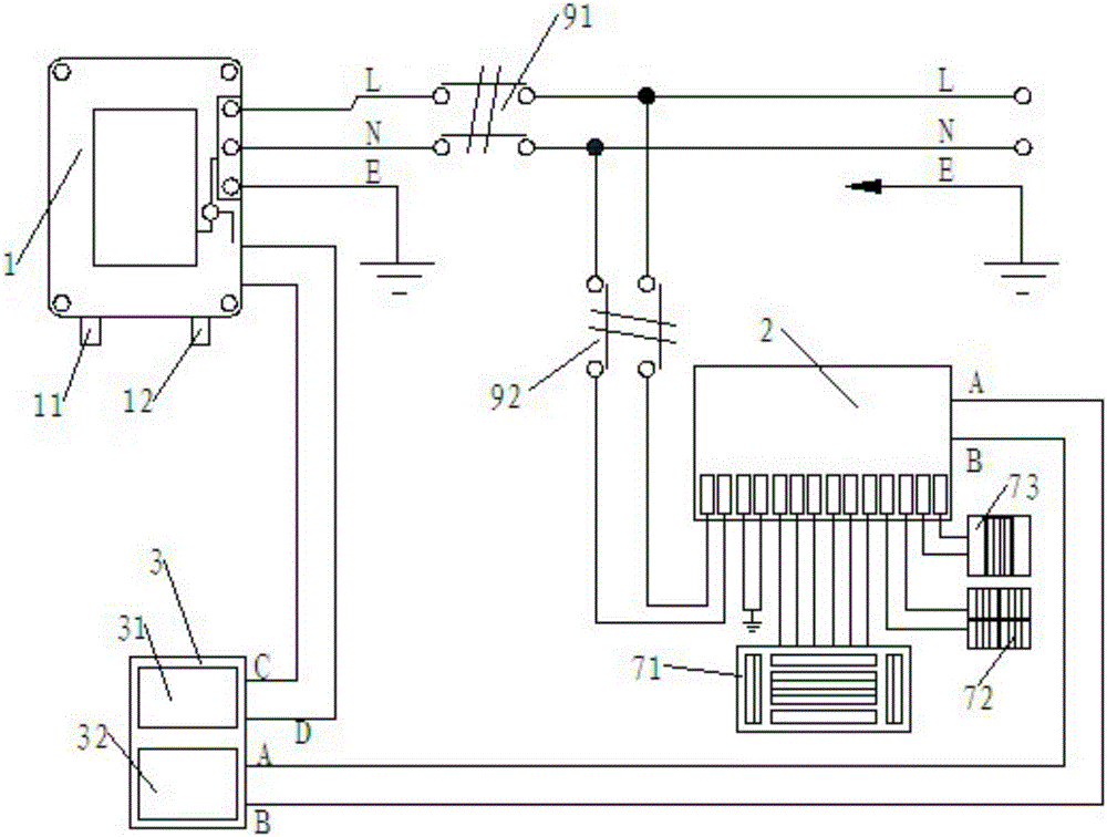
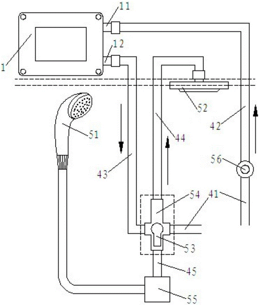
[0038] See attached picture. The integrated suspended ceiling structure provided by the embodiment of the present invention includes a keel frame 61 fixedly installed under the ceiling, a panel buckled on the keel frame, an instant water heater 1 with a cold water inlet 11 and a hot water outlet 12 , a buckle mounted on the keel The functional modules on the frame and the terminal control box 2 electrically connected with the functional modules.

[0039] The instant water heater is provided with a cold water inlet 11 , a hot water outlet 12 , a junction box 13 and an outlet pipe 14 . A pressure relief valve is installed on the outlet pipe 14. When the water pressure exceeds the maximum pressure of the instant water heater, dripping water will appear at the pressure relief valve. The pressure inside the water heater.

[0040] In the embodimen...


PUM


Abstract

The invention discloses an integrated ceiling structure. The integrated ceiling structure comprises a keel frame, a panel, an instantaneous water heater, function modules and a terminal control box, wherein the keel frame is fixedly installed, the panel is buckled on the keel frame, the instantaneous water heater is provided with a cold water inlet and a hot water outlet, the function modules are buckled on the keel frame, and the function modules and the terminal control box are electrically connected together. The instantaneous water heater is fixedly installed above the keel frame, the terminal control box is fixedly installed on the keel frame and located above the panel, both the instantaneous water heater and the terminal control box are electrically connected with a control panel with an operating box together, the instantaneous water heater and the operating box are electrically connected together through a first data line, and the terminal control box and the operating box are electrically connected together through a second data line. According to the integrated ceiling structure, a traditional integrated ceiling structure is improved, the function modules are integrally installed on the panel in a concealed mode, after the function modules are installed, the integrated ceiling structure is more attractive and more elegant in whole, and the problem that the instantaneous water heater and the panel are not coordinated is solved.

Description

technical field [0001] The invention relates to the technical field of toilet decoration, in particular to an integrated ceiling structure integrating various functional modules. Background technique [0002] With the improvement of living standards, people's requirements for quality of life are also increasing. Among them, bathing and bathing are indispensable activities in people's daily life. Bathing or bathing can help people relieve fatigue and promote blood circulation in the body. It can be more comfortable when bathing, and people have higher and higher requirements for bathing and bathing equipment. [0003] The instant water heater works in the way of direct heating. The electric heating element is placed in the groove of the groove plate. When the cold water flows through the groove, it can directly flow through the surface of the electric heating element to be heated. The water groove is like a snake, and the cold water flows into it. After the sink is gradually...

Claims


Application Information

Patent Timeline
Patent Type & Authority Patents(China)
IPC IPC(8): E04B9/04E04F13/074F24H9/20
Inventor 徐惠峰
Owner JIAXING GELER INTEGRATED CEILING TECH
Why Eureka
Try Eureka