A blue-phase liquid crystal display with low driving voltage and continuously controllable viewing angle
A low driving voltage, blue-phase liquid crystal technology, applied in static indicators, instruments, nonlinear optics, etc., can solve the problems of inconsistent driving curves, complicated display technology, high driving voltage, etc., achieve continuous controllable viewing angle, realize viewing angle, The effect of low driving voltage
- Summary
- Abstract
- Description
- Claims
- Application Information
AI Technical Summary
Problems solved by technology
Method used
Image
Examples
Embodiment 1
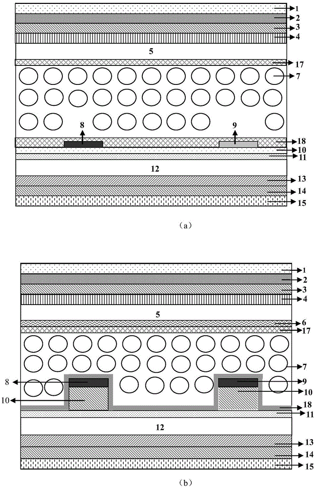
[0044] like figure 1 As shown in (a), it is a traditional FIS-driven blue-phase liquid crystal display structure, which includes from top to bottom: upper polarizer 1, upper λ / 2 biaxial film 2, upper λ / 2 negative A wave plate 3, upper λ / 4 Positive A wave plate 4, upper glass substrate 5, first protective layer 17, blue phase liquid crystal 7, second protective layer 18, first Pixel electrode 8 and second Pixel electrode 9, transparent raised layer 10, Common electrode 11, the lower glass substrate 12, the lower λ / 4 negative A wave plate 13, the lower λ / 2 positive A wave plate 14, and the lower polarizer 15.
[0045] like figure 1 As shown in (b), it is the blue-phase liquid crystal display structure of this embodiment, which includes from top to bottom: upper polarizer 1, upper λ / 2 biaxial film 2, upper λ / 2 negative A wave plate 3, upper λ / 4 Positive A wave plate 4, upper glass substrate 5, first Common electrode 6, first protective layer 17, blue phase liquid crystal 7, s...
Embodiment 2
[0068] Figure 6 According to the electrode structure of embodiment 2, the whole pixel is divided into two parts, the purpose is to make the viewing angle more symmetrical, and facilitate the connection of all pixel electrodes, and the corresponding transparent raised layer under the pixel electrodes is also changed in the same way.
[0069]The difference between this embodiment and Embodiment 1 is that the transparent protrusions 10 , the first Pixel electrodes 8 and the second Pixel electrodes 9 in this embodiment have a "horizontal and vertical" structure. That is to say, the overall shape of the transparent protrusion 10 covered with the first Pixel electrode 8 or the second Pixel electrode 9 on the second Common electrode 11 is viewed from above, and the entire pixel is divided into upper and lower parts. The first Pixel electrode and the second Pixel electrode are arranged in a horizontal comb-tooth shape with opposite directions and staggered arrangement. In the upper h...
Embodiment 3
[0076] Figure 10 It is the electrode structure diagram of the full pixel in embodiment 3. The electrode structure is a "zigzag" structure, and the purpose is also to realize the symmetry of the viewing angle. Correspondingly, the transparent raised layer under the electrode should be changed accordingly.
[0077] The difference between this embodiment and Embodiment 1 is that the transparent protrusion 10 , the first Pixel electrode 8 and the second Pixel electrode 9 in this embodiment have a zigzag structure, and the included angle of the "zigzag" is 90°. The corresponding transparent protrusions are also changed into zigzag transparent protrusions. The included angle of the word "Zhi" is also 90°. The first Pixel electrode 8 and the second Pixel electrode 9 are located above the transparent protrusion.
[0078] The parts not described in this embodiment are the same as those in Embodiment 1.
[0079] In this embodiment, in the wide viewing angle mode, the voltage applied...
PUM
| Property | Measurement | Unit |
|---|---|---|
| thickness | aaaaa | aaaaa |
| height | aaaaa | aaaaa |
| thickness | aaaaa | aaaaa |
Abstract
Description
Claims
Application Information
 - R&D
- Intellectual Property
- Life Sciences
- Materials
- Tech Scout
- Unparalleled Data Quality
- Higher Quality Content
- 60% Fewer Hallucinations
Browse by: Latest US Patents, China's latest patents, Technical Efficacy Thesaurus, Application Domain, Technology Topic, Popular Technical Reports.
© 2025 PatSnap. All rights reserved.Legal|Privacy policy|Modern Slavery Act Transparency Statement|Sitemap|About US| Contact US: help@patsnap.com


