Electrostatic chucks and plasma processing equipment

A technology of electrostatic chuck and chuck body, applied in the direction of circuits, discharge tubes, electrical components, etc., can solve the problems of reducing the quality of processing, increasing heat loss of heating elements 16, and uneven chip temperature, so as to reduce heat loss , Improve heating uniformity, facilitate installation and replacement

Active Publication Date: 2016-06-08
BEIJING NAURA MICROELECTRONICS EQUIP CO LTD
View PDF3 Cites 0 Cited by
  • Summary
  • Abstract
  • Description
  • Claims
  • Application Information

AI Technical Summary

Problems solved by technology

[0010] One, because part of the heat generated by the heating element 116 will be conducted to the insulating ring 154, the heat loss of the heating element 16 will increase, thereby reducing the heating efficiency of the electrostatic chuck
Moreover, since the insulating ring 154 is only in contact with the edge region of the bottom of the chuck body 110, the heat loss rate of the edge region of the chuck body 110 is greater than that of the center region, which makes the temperature of the chuck body 110 uneven, thereby Make the temperature of the wafer uneven, thereby reducing the quality of processing
[0011] Second, since the two ends of the expansion joint 140 are respectively fixedly connected to the chuck main body 110 and the platform assembly 130 by welding, the installation process of the expansion joint 140 is complicated, and it is difficult to disassemble and replace the expansion joint 140, which not only improves It reduces the processing difficulty of the electrostatic chuck and increases the cost of using the electrostatic chuck

Method used


Image

  • Electrostatic chucks and plasma processing equipment
  • Electrostatic chucks and plasma processing equipment
  • Electrostatic chucks and plasma processing equipment

Examples


Embodiment Construction

[0053] In order for those skilled in the art to better understand the technical solution of the present invention, the electrostatic chuck and the plasma processing equipment provided by the present invention will be described in detail below with reference to the accompanying drawings.

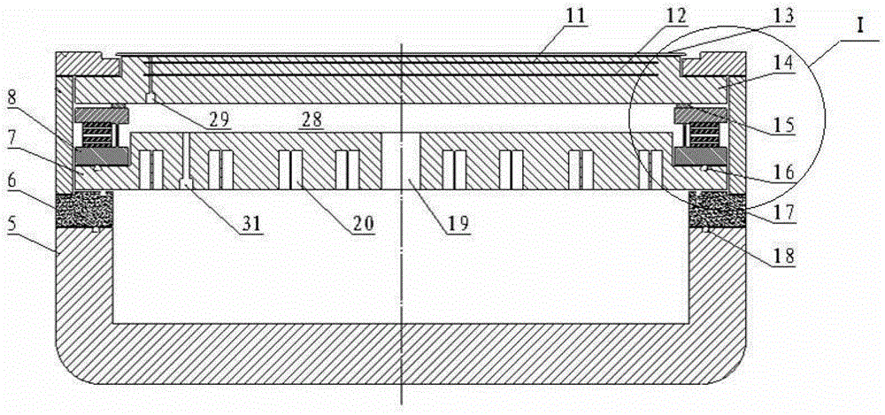
[0054] Figure 3a A cross-sectional view of the electrostatic chuck provided by the present invention. Figure 3b for Figure 3a Partial enlarged view of region I. Please also refer to Figure 3a with Figure 3b , the electrostatic chuck includes a chuck for carrying a workpiece 13 to be processed, a base 5 and a thermal insulation assembly 8 . Wherein, the chuck includes a chuck body 14 , an electrostatic electrode 11 and a heating unit 12 arranged in the chuck body 14 . The electrostatic electrode 11 is connected to a DC power supply (not shown in the figure), and the DC power supply provides energy to the electrostatic electrode 11 to fix the processed workpiece 13 on the chuck by ele...


PUM


Abstract

Provided is an electrostatic chuck, comprising a chuck for bearing a to-be-processed workpiece (13), and a base (5); a heat insulation assembly (8) is disposed between the chuck (14) and the base (5); the heat insulation assembly (8) comprises an upper annular plate (25), a lower annular plate (27), and an expandable heat insulation ring (22); the upper annular plate (25) and the lower annular plate (27) are both annular plates, and are oppositely disposed in the axial direction of the electrostatic chuck; the expandable heat insulation ring (22) is a hollow thin-walled tube structure, and is fixed between the upper annular plate (25) and the lower annular plate (27); the axial direction of the expandable heat insulation ring is consistent with that of the upper annular plate (25) and the lower annular plate (27), such that the expandable heat insulation ring (22) can adapt to the deformation of the heated chuck and the base (5). In addition, the electrostatic chuck is easy to process and replace, thus reducing the use cost of the electrostatic chuck.

Description

technical field [0001] The invention relates to the field of semiconductor equipment manufacturing, in particular to an electrostatic chuck and plasma processing equipment. Background technique [0002] In the process of manufacturing integrated circuits (IC) and microelectromechanical systems (MEMS), especially in the process of implementing plasma etching (ETCH), physical vapor deposition (PVD), chemical vapor deposition (CVD), etc., often Electrostatic chucks are used to fix, support and heat processed workpieces such as wafers, provide DC bias voltage for wafers and control the temperature of the wafer surface. [0003] figure 1 It is a schematic diagram of the structure of a typical electrostatic chuck. Such as figure 1 As shown, the electrostatic chuck includes an insulating layer 1 , a heater 2 and an aluminum base 3 stacked in sequence from top to bottom. Among them, the insulating layer 1 adopts AL 2 o 3 or ALN and other ceramic materials, and a DC electrode l...

Claims


Application Information

Patent Timeline
Patent Type & Authority Patents(China)
IPC IPC(8): H01L21/683H01J37/32
CPCH01L21/6831H01L21/67103
Inventor 彭宇霖
Owner BEIJING NAURA MICROELECTRONICS EQUIP CO LTD
Why Eureka
Try Eureka