
Device and method for achieving Ethernet topology automatic switchover

An automatic switching, Ethernet technology, applied in the field of communication, can solve the problem of unable to forward data packets at wire speed, etc., to achieve the effect of easy real-time configuration, convenient management, and wire speed forwarding

Active Publication Date: 2014-05-14
TP-LINK
View PDF5 Cites 4 Cited by
  • Summary
  • Abstract
  • Description
  • Claims
  • Application Information

AI Technical Summary

Problems solved by technology

[0004] The purpose of the present invention is to provide a device and method for automatic switching of Ethernet topology, aiming to solve the problem that the prior art cannot meet the requirements of wire-speed forwarding data packets

Method used


Image

  • Device and method for achieving Ethernet topology automatic switchover
  • Device and method for achieving Ethernet topology automatic switchover
  • Device and method for achieving Ethernet topology automatic switchover

Examples


Embodiment 1

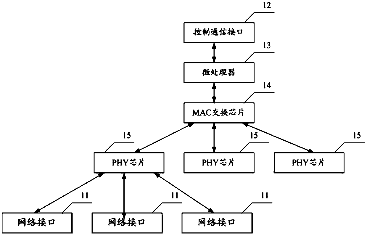
[0022] see figure 1 The device for realizing automatic switching of Ethernet topology provided by Embodiment 1 of the present invention includes a plurality of network interfaces 11 for external network cable access and a control communication interface 12. The network interface 11 is an Ethernet interface or an SFP optical fiber interface, etc., so The control communication interface 12 is a communication interface such as an Ethernet interface, a serial port, etc., and the control communication interface 12 is used to operate the device to realize automatic Ethernet topology switching. The device further includes a microprocessor 13 , a Media Access Control (Media Access Control, MAC) switch chip 14 and multiple physical layer (Physical Layer, PHY) chips 15 . The microprocessor 13 is connected to the control communication interface 12 and the MAC switching chip 14 respectively, and the MAC switching chip 14 is connected to a plurality of PHY chips 15 respectively, and each P...

Embodiment 2

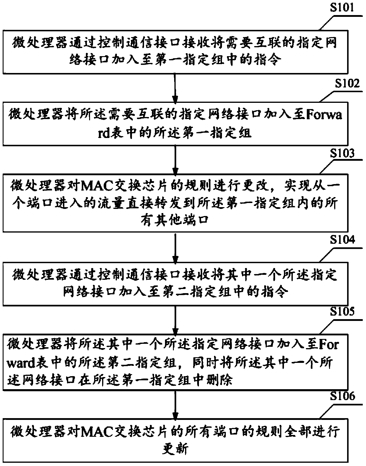
[0032] see figure 2 Embodiment 2 of the present invention provides a method for realizing automatic switching of Ethernet topology. The method is executed by the device for realizing automatic switching of Ethernet topology provided in Embodiment 1 of the present invention. The method includes the following steps:

[0033] S101. The microprocessor receives an instruction to add specified network interfaces that need to be interconnected to the first specified group through the control communication interface;


PUM


Abstract

The invention belongs to the field of communication, and provides a device for achieving Ethernet topology automatic switchover. The device comprises multiple network interfaces for external network cables to be connected, a control communication interface, a microprocessor, an MAC exchange chip and multiple PHY chips. The control communication interface is used for operating the device to achieve the Ethernet topology automatic switchover. The microprocessor is used for receiving and processing of instructions and return of results, is also used for generating and maintaining a network interface forwarding table, and controls the MAC exchange chip to modify the forwarding rules of corresponding network interfaces. The network interface forwarding table uses a group as a unit, each network interface can be only in one group, and for all the network interfaces in one group, flow of each network interface will be forwarded to the other network interfaces. According to the device for achieving the Ethernet topology automatic switchover, an Ethernet topology automatic switchover function can be achieved, manual operation is not needed, wire-speed forwarding can be further achieved, under the circumstance that performance is guaranteed, topological transformation is flexible, management is convenient, and real-time configuration is convenient to carry out.

Description

technical field [0001] The invention relates to the communication field, in particular to a device and a method for realizing automatic Ethernet topology switching. Background technique [0002] In an Ethernet network, especially in an Ethernet topology for testing, it is often necessary to adjust the topology of the Ethernet. The solution in the prior art is to use a switch to divide two ports of the switch into one 802.1Q virtual local area network (Virtual Local Area Network, VLAN), and to re-divide the other two ports into one 802.1Q VLAN during topology switching. For example, devices under test 1 and 2 are respectively connected to port 1 and port 2 of the switch, and devices under test 3 and 4 are connected to ports 3 and 4 of the switch. In topology I, port 1 and port 2 are divided into one 802.1Q VLAN , port 3 and port 4 are assigned to another 802.1Q VLAN for topology switching. In topology II, the 802.1Q VLAN is reclassified. Another 802.1Q VLAN. [0003] Howev...

Claims


Application Information

Patent Timeline
Patent Type & Authority Applications(China)
IPC IPC(8): H04L12/46H04L12/24H04L12/751H04L45/02
Inventor 赵振
Owner TP-LINK
Learn More