Constant temperature and constant humidity storage cabinet

A constant temperature and humidity, storage cabinet technology, used in cabinets, dispersed particle separation, household appliances and other directions, can solve problems such as difficulty in meeting extreme dryness, ultra-low humidity, inability to achieve uninterrupted dehumidification, and unfavorable green environmental protection concepts. To achieve the effect of stable humidity, short stroke and complete regeneration

Inactive Publication Date: 2014-05-21
深圳市华宇现代科技有限公司
View PDF6 Cites 7 Cited by
  • Summary
  • Abstract
  • Description
  • Claims
  • Application Information

AI Technical Summary

Problems solved by technology

[0006] However, the constant temperature and humidity storage cabinets in the prior art are usually a single dehumidification chamber in the structural design of the dehumidification system, which has low dehumidification efficiency and high energy consumption, especially it is difficult to meet the requirements of extremely dry and ultra-low humidity. In addition, when the dry material is regenerated, the dehumidification work needs to be stopped, and the function of uninterrupted dehumidification cannot be realized
These defects have caused bottlenecks in some special applications of constant temperature and humidity storage cabinets, and are not conducive to the advocacy of the concept of green environmental protection.

Method used


Image

  • Constant temperature and constant humidity storage cabinet
  • Constant temperature and constant humidity storage cabinet
  • Constant temperature and constant humidity storage cabinet

Examples


Embodiment Construction

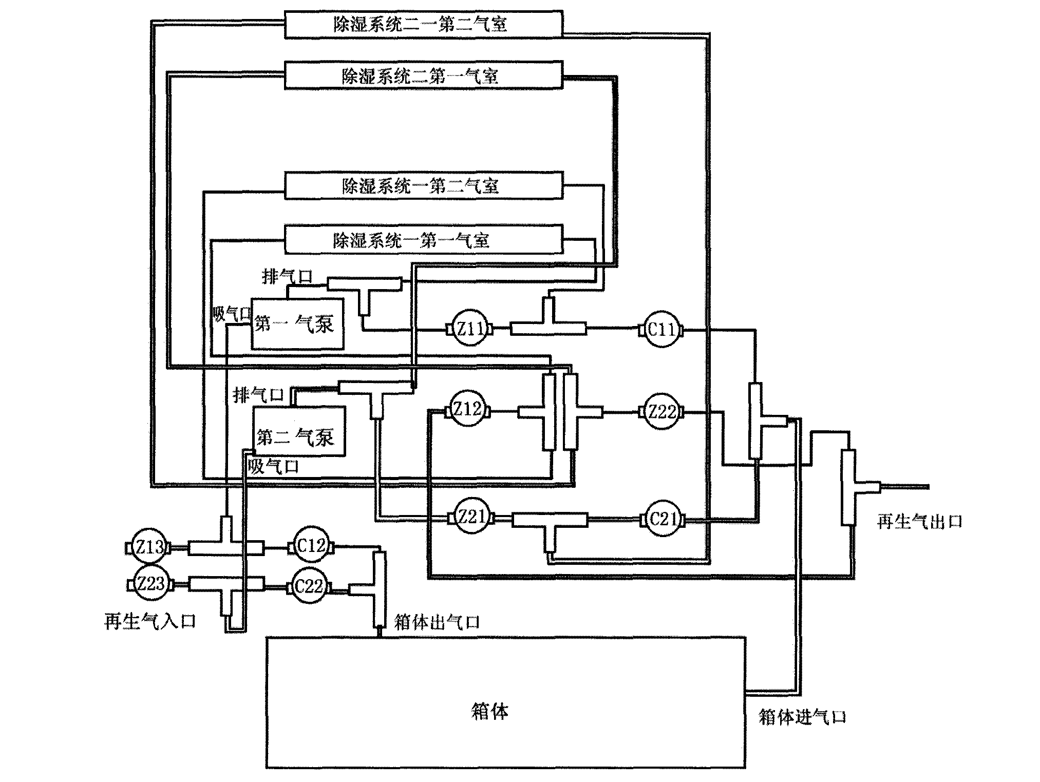
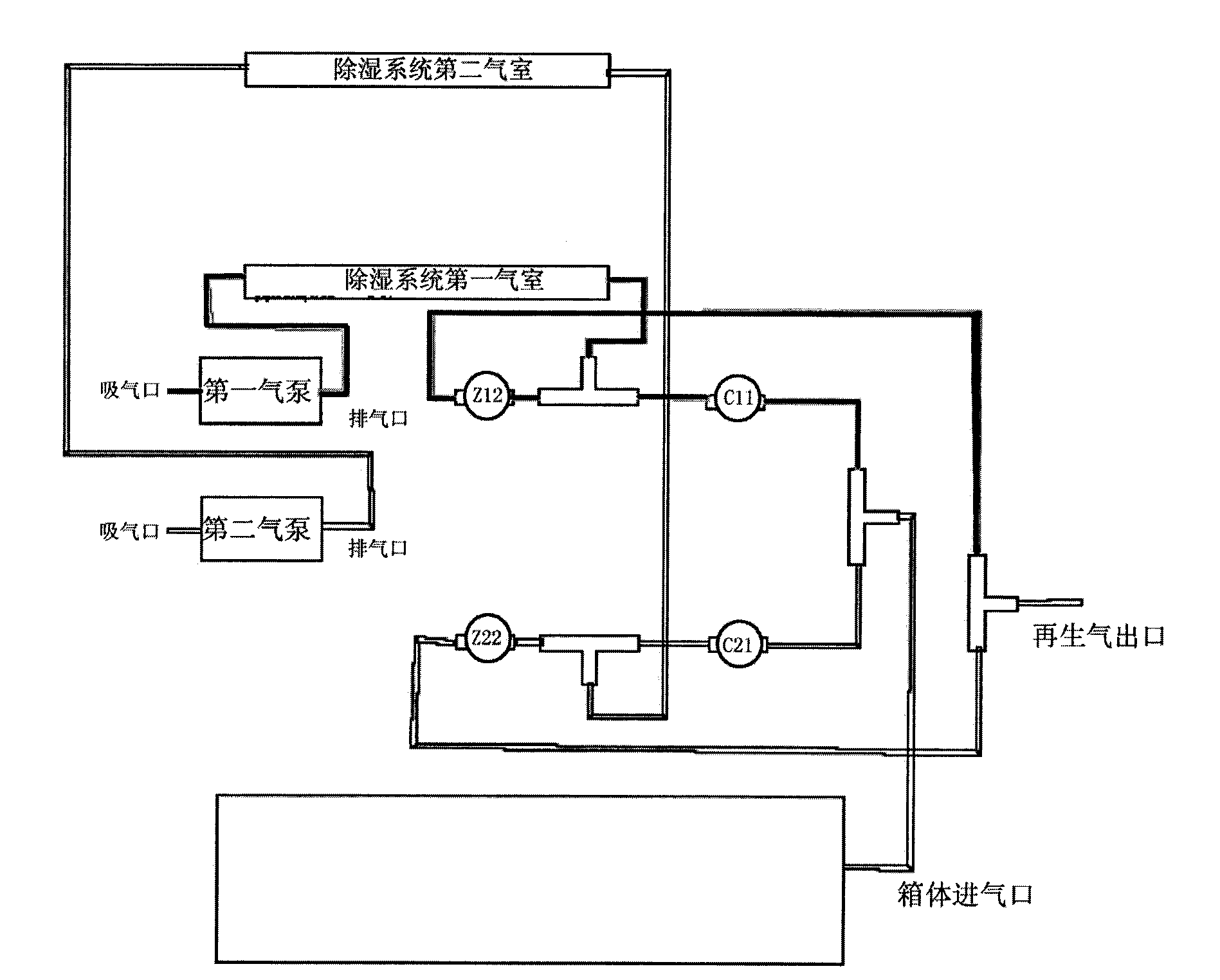
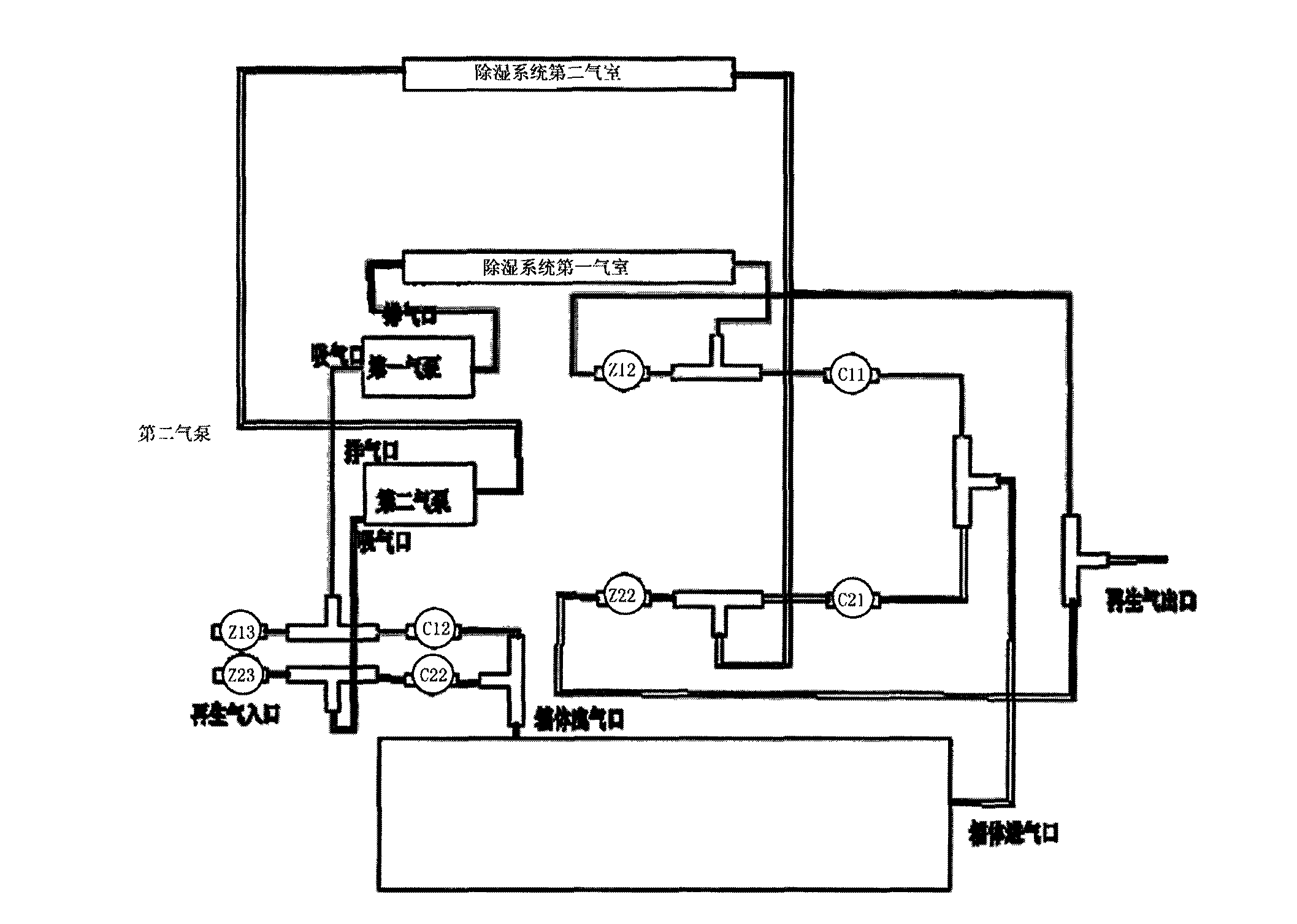
[0026] The present invention will be described in further detail below in conjunction with the accompanying drawings and specific embodiments.

[0027] The constant temperature and humidity storage cabinet involved in the present invention includes a box for storing items, a constant temperature device for controlling the temperature inside the box, a dehumidification device for controlling the humidity inside the box, and an automatic control device for controlling the operation of the above-mentioned devices; the automatic control device It can be any technology in the prior art, such as a single-chip microcomputer control system, etc., and can include a human-machine interface such as an LCD display system that is convenient for user operation. The constant temperature device may be any technology in the prior art, such as a compressor cooling system and the like. Of course, a humidifying device can also be added to the technology of the present invention, and the humidifyi...


PUM


Abstract

The invention discloses a constant temperature and constant humidity storage cabinet. The constant temperature and constant humidity storage cabinet comprises a box body, a thermostat for controlling the temperature of the box body, a dehumidifier for controlling the humidity of the box body and an automatic control device for controlling the devices to operate; the dehumidifier comprises at least two sets of dehumidifying systems connected in parallel; each dehumidifying system comprises an air pump and more than one air chambers hermetically containing regenerated drying materials and heating modules. The scheme that multiple dehumidifying systems are connected in parallel is adopted, so other dehumidifying systems can normally work when one set of system is subjected to regeneration, continuous uninterrupted dehumidifying is realized to ensure the unchanged stable humidity in the box body; each set of dehumidifying system adopts a multi-air chamber serial connection structure during dehumidifying, so dehumidifying gases can dehumidify in a grading mode, the dryness is improved by multiple levels, and the dryness of the gas achieving the cabinet body is higher; each air chamber is independently regenerated during regeneration, so humid gases generated by the regeneration are short in travel without mutual crossing, and the regeneration is thorough; a dehumidifying inner circulation and regeneration outer gas production design is adopted, so the cleanliness of air in the box body is ensured, the drying speed is accelerated, and the regeneration is efficient, energy-saving, low-carbon and environment-friendly.

Description

technical field [0001] The invention relates to the technical field of article storage equipment, in particular to a storage cabinet, in particular to a microcomputer-controlled storage cabinet with constant temperature and humidity functions. Background technique [0002] The air in the natural environment contains a certain amount of moisture, and the air humidity refers to the degree of moisture in the air, which can be expressed by relative humidity (RH). %RH is the quantitative unit of relative humidity. The higher the value, the more humid the air environment under a certain temperature condition; during the moldy rain season, the humidity in many areas is often as high as 70% RH, usually exceeding 60% RH is the growth of mold The condition is that every family and business should pay attention to dehumidification and moisture-proof issues; on the other hand: in winter, the air is very dry, especially in the north, the air dryness will even be lower than 10% RH, such a...

Claims


Application Information

Patent Timeline
Patent Type & Authority Applications(China)
IPC IPC(8): A47B81/00B01D53/26
Inventor 丁斌秦水源
Owner 深圳市华宇现代科技有限公司
Why Eureka
Try Eureka