Field pipeline groove cutting machine

A cutting machine and pipeline technology, used in metal processing equipment, milling machine equipment, manufacturing tools, etc., can solve the problem of not effectively improving the cutting efficiency and quality of pipeline grooves, improve cutting quality and pipeline welding quality, and increase flexibility. , the effect of improving quality

Inactive Publication Date: 2014-05-21
NORTH CHINA ELECTRIC POWER UNIV (BAODING)
View PDF5 Cites 6 Cited by
  • Summary
  • Abstract
  • Description
  • Claims
  • Application Information

AI Technical Summary

Problems solved by technology

This patented technology can reduce the labor intensity of workers, but it ca

Method used


Image

  • Field pipeline groove cutting machine
  • Field pipeline groove cutting machine
  • Field pipeline groove cutting machine

Examples


Embodiment 1

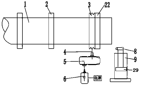
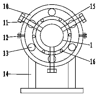
[0020] On-site pipeline bevel cutting machine of the present invention such as figure 1 Shown, comprise 2 chucks 2, driving chuck 22, belt pulley 3, speed changer 5, motor 6 and milling cutter equipment. Such as image 3 , Figure 4 Shown, active chuck and chuck are made of outer ring 10, inner ring 15 and support 14, and outer ring and inner ring are coaxially installed, and bearing 13 is housed between outer ring and inner ring, and bearing is ball bearing. The outer ring 10 is formed by buckling two semicircles, the two parts of the outer ring are fixed by bolts 12 , and the lower half of the outer ring is connected with the bracket 14 . The inner ring is provided with a positioning screw 11, and the positioning screw passes through the threaded hole 17 of the inner ring to clamp the pipeline to be processed. The inner ring of the active chuck is provided with screw holes 16, and the inner ring of the active chuck is fixedly connected with the belt pulley by bolts. The ...

Embodiment 2

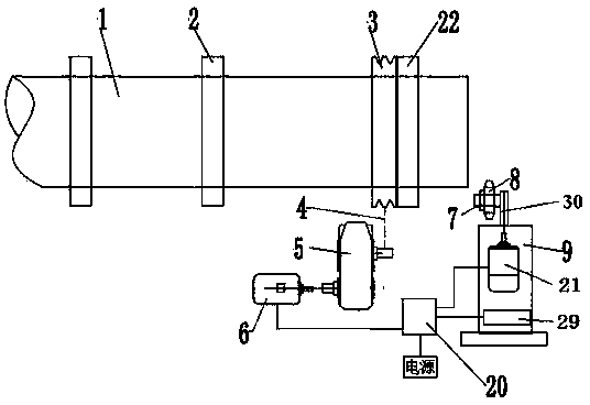
[0023] Another embodiment of the present invention is as figure 2 Shown, comprise 2 chucks 2, driving chuck 22, belt pulley 3, speed changer 5, motor 6, controller 20 and milling cutter equipment. Such as image 3 , Figure 4 Shown, active chuck is made of outer ring 10, inner ring 15 and support 14, and outer ring and inner ring are coaxially installed, and bearing 13 is housed between outer ring and inner ring, and bearing is roller bearing. The outer ring 10 is formed by buckling two semicircles, the two parts of the outer ring are fixed by bolts 12 , and the lower half of the outer ring is connected with the bracket 14 . The inner ring is provided with a positioning screw 11, and the positioning screw passes through the threaded hole 17 of the inner ring to clamp the pipeline to be processed. Such as Figure 5 , Image 6 As shown, the chuck is composed of an inner ring 15, a roller 18 and a roller bracket 19. The inner ring is provided with a positioning screw 11, th...

Embodiment 3

[0025] The third embodiment of the present invention is as Figure 8 Shown, comprise 3 chucks 2, driving chuck 22, belt pulley 3, speed changer 5, motor 6 and milling cutter equipment. The left side of active chuck 22 is provided with 1 chuck, and the right side is provided with two chucks. Milling cutter equipment comprises groove milling cutter 8, milling cutter case 9, milling cutter moving mechanism 29, pipeline cutter 32, cutter motor and cutter moving mechanism 33. The milling cutter moving mechanism 29 and the cutter moving mechanism are installed in the milling cutter box 9, the bevel milling cutter is installed on the milling cutter moving mechanism, and the pipeline cutter is installed on the cutter moving mechanism by the cutter bracket 34. The cutter motor is installed on the cutter bracket, and the pipeline cutter is coaxially connected with the cutter motor. The bevel milling cutter 8 and the pipeline cutter 32 on the milling cutter box can exchange positions w...


PUM


Abstract

The invention relates to a field pipeline groove cutting machine which comprises a chuck, a driving chuck, a speed changer, a motor, a belt pulley and a milling cutter device, wherein the chuck and the driving chuck are respectively formed by an outer ring, an inner ring and a bracket; the outer ring and the inner ring are arranged in a coaxial way, a bearing is arranged between the outer ring and the inner ring, and the inner ring is provided with a set screw; the inner ring of the driving chuck is provided with a screw hole, and the inner ring is fixedly connected with the belt pulley by a bolt; the motor is connected with the speed changer by a gear; the speed changer is connected with the belt pulley by a transmitting belt; the milling cutter device comprises a groove milling cutter, a milling cutter box and a milling cutter moving mechanism; the milling cutter moving mechanism is arranged in the milling cutter box; the groove milling cutter is arranged on the milling cutter moving mechanism. According to the field pipeline groove cutting machine, the processed pipeline is fixed on the groove cutting machine by the chuck and the driving chuck and is driven to rotate by the motor through the speed changer, and groove cutting is carried out on the pipeline by the groove milling cutter, so that the pipeline groove cutting quality and the pipeline welding quality are improved, and pipeline laying construction efficiency is increased.

Description

technical field [0001] The invention belongs to the technical field of pipeline equipment installation and welding, and relates to an on-site pipeline bevel cutting machine. Background technique [0002] Petroleum and chemical companies design and install a large number of process pipelines to meet the needs of production and operation. The laying of pipelines is to weld the pipes together to form pipelines. At the construction site of laying pipelines, it is necessary to cut grooves at the joints of pipelines to facilitate butt welding of pipelines. The traditional method is to cut grooves by gas cutting. When laying a long-distance oil pipeline, the number of pipeline grooves that need to be processed is huge. Using the conventional gas cutting method to process the grooves is not only slow, but also difficult to control the quality of the grooves. Poor quality of the grooves will increase the difficulty of subsequent welding, resulting in Slow welding speed, poor quality...

Claims


Application Information

Patent Timeline
IPC IPC(8): B23C3/12
Inventor 赵婷
Owner NORTH CHINA ELECTRIC POWER UNIV (BAODING)
Why Eureka
Try Eureka