Fixture structure for machining herringbone groove in plunger part

A technology of herringbone grooves and plugs, which is applied in the direction of manufacturing tools, metal processing equipment, metal processing machinery parts, etc., to achieve the effect of ensuring stability, high processing efficiency and simple structure

Active Publication Date: 2014-05-21
无锡威孚马山油泵油嘴有限公司
View PDF11 Cites 0 Cited by
  • Summary
  • Abstract
  • Description
  • Claims
  • Application Information

AI Technical Summary

Problems solved by technology

In order to meet customer requirements, it is now necessary to process a "herringbone" groove on the plunger. The existing clamping method cannot meet the processing of the above groove, so it is urgent to design a new fixture structure.

Method used


Image

  • Fixture structure for machining herringbone groove in plunger part

Examples


Embodiment Construction

[0010] The specific implementation manner of the present invention will be described below in conjunction with the accompanying drawings.

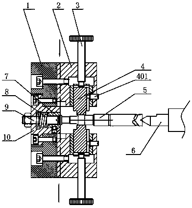
[0011] Such as figure 1 As shown, a fixture structure for processing herringbone grooves of plunger parts includes a fixture body 1 and a flat seat 2 that are fixed to each other. In the top seat 10, the spring 8 is set on the outer periphery of the set screw 9, and at the end of the set screw 9, the female top 7 is also installed in the top seat 10; Locking and positioning by the locking screw 401 , the knurled screw 3 is symmetrically installed on both sides of the flat seat 2 , and its end extends into the flat seat 2 and abuts against the flat post 4 .

[0012] Concrete work process of the present invention is as follows:

[0013] First, clamp body 1 of the present invention is installed on the chuck of the machine tool, then one end of plunger part 5 is abutted against female tip 7, female tip 7 is stressed and elastically lifted by...


PUM


Abstract

The invention relates to a fixture structure for machining a herringbone groove in a plunger part. The fixture structure comprises a fixture body and a flat seat which are fixedly connected with each other, wherein a foot block is concentrically arranged in the fixture body, a positioning screw is arranged in the foot block in a penetrating manner, a spring is sleeved on the periphery of the positioning screw, a female tip is further arranged in the foot block at the end of the positioning screw, flat columns are symmetrically arranged in the flat seat, and knurled screws are symmetrically arranged on two sides of the flat seat, and the end parts of the knurled screws extend into the flat seat and prop against the flat columns. The fixture structure is simple, and the knurled screws are rotated in the flat seat to drive the flat columns to move and clamp the plunger part, so that the center of the plunger part and the rotation center of a machine tool spindle are in a same straight line, and by adopting the female tip, the end part of the plunger part is effectively positioned, the machining stability of the herringbone groove in the plunger part is ensured, problems of cutter relieving and cutter vibration can be avoided, one-time machining for the herringbone groove in the plunger part can be effectively realized, and the machining efficiency is high.

Description

technical field [0001] The invention relates to a tooling fixture, in particular to a fixture structure for processing a herringbone groove of a plunger piece. Background technique [0002] The plunger coupling is formed by the precision fit of the plunger and the plunger sleeve, and the oil outlet valve coupling (composed of the oil outlet valve and the oil outlet valve seat) is installed above it. In order to meet customer requirements, it is now necessary to process a "herringbone" groove on the plunger. The existing clamping method cannot meet the processing of the above groove, so it is urgent to design a new fixture structure. Contents of the invention [0003] In view of the above existing problems, the applicant has conducted research and provided a fixture structure for processing the herringbone groove of the plunger, which effectively realizes the one-time processing of the herringbone groove of the plunger and has high processing efficiency. [0004] The ...

Claims


Application Information

Patent Timeline
Patent Type & Authority Applications(China)
IPC IPC(8): B23Q3/00
CPCB23Q3/00
Inventor 徐俊伟
Owner 无锡威孚马山油泵油嘴有限公司
Why Eureka
Try Eureka