
Novel sewage treatment device

A sewage treatment device and a new technology, applied in the field of new sewage treatment devices, can solve the problems of restricting the promotion and application of denitrification process, complex operation management, high infrastructure costs, etc., to ensure the sludge residence time, ensure the sludge concentration, solve the The effect of sludge clogging

Active Publication Date: 2014-05-21
ZHEJIANG DEAN TECH
View PDF9 Cites 5 Cited by
  • Summary
  • Abstract
  • Description
  • Claims
  • Application Information

AI Technical Summary

Problems solved by technology

However, in the implementation process, due to the large number of structures to be treated, the return of sludge, and the large output, resulting in large investment, high energy consumption, complex operation management, high operating costs, large floor space, and high infrastructure costs, etc.
These factors seriously restrict the promotion and application of denitrification technology in new or renovated sewage treatment plants

Method used


Image

  • Novel sewage treatment device
  • Novel sewage treatment device
  • Novel sewage treatment device

Examples


Embodiment Construction

[0044] The present invention will be further described in detail below with reference to the embodiments of the accompanying drawings.

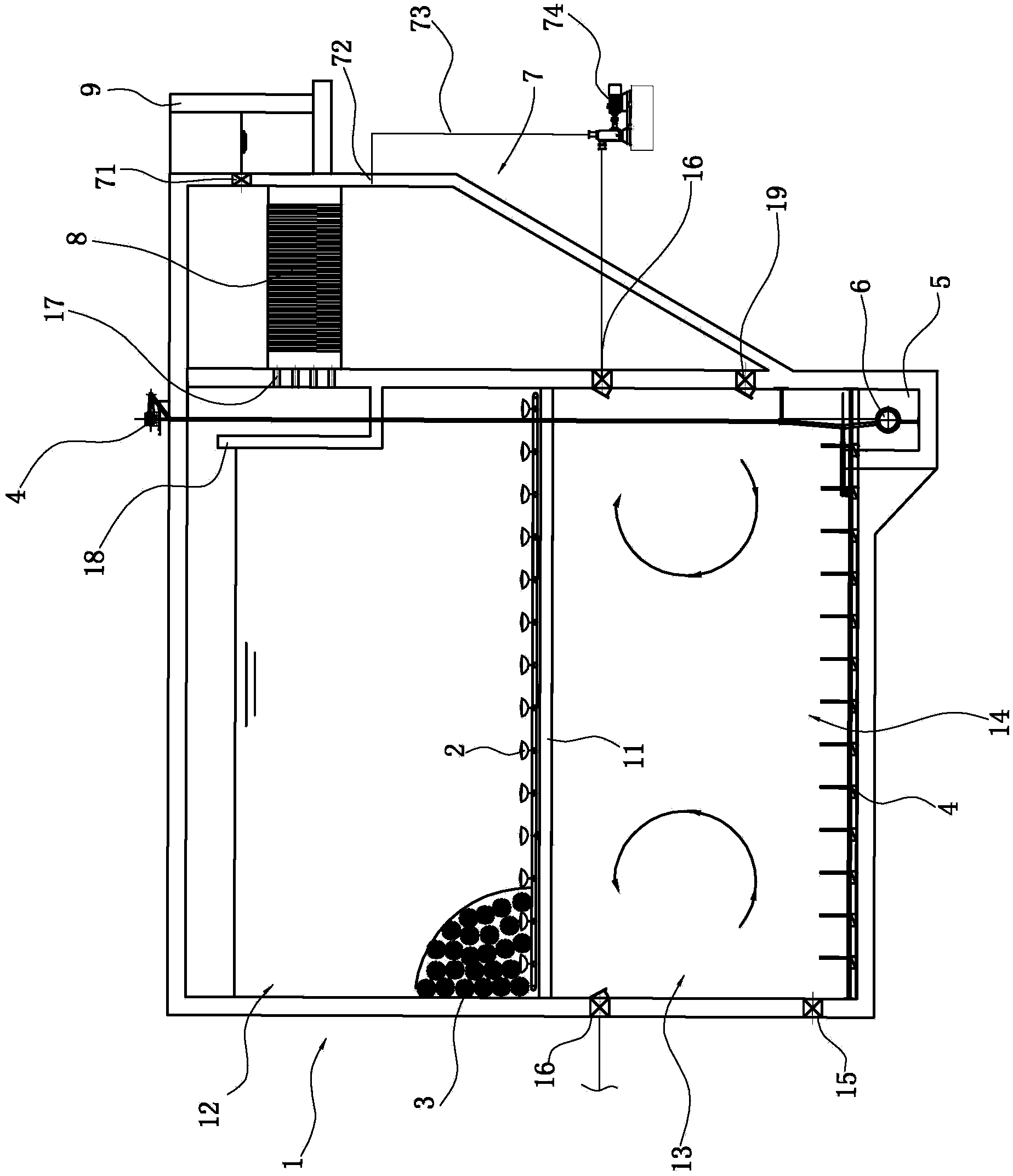
[0045] like Figure 1 to Figure 17 As shown, the new sewage treatment device includes:

[0046] Reaction tank 1, a place for biochemical treatment of sewage, which is provided with a transverse partition 11 to separate the inner cavity of the reaction tank into an aerobic zone 12 located above, an anaerobic anoxic zone 13 located in the upper part of the lower part, and a Lower lower anaerobic zone 14.

[0047] The structural design corresponding to the anaerobic section:

[0048] The side wall of the reaction tank is provided with a water inlet hole 15 for sewage to enter the reaction tank at a position close to the bottom of the reaction tank. There is a pushing device 6 for pushing the sludge to the outside of the mud hopper. The pushing device in this embodiment adopts a screw conveyor 6, and the screw conveyor sends the sludge out of ...


PUM


Abstract

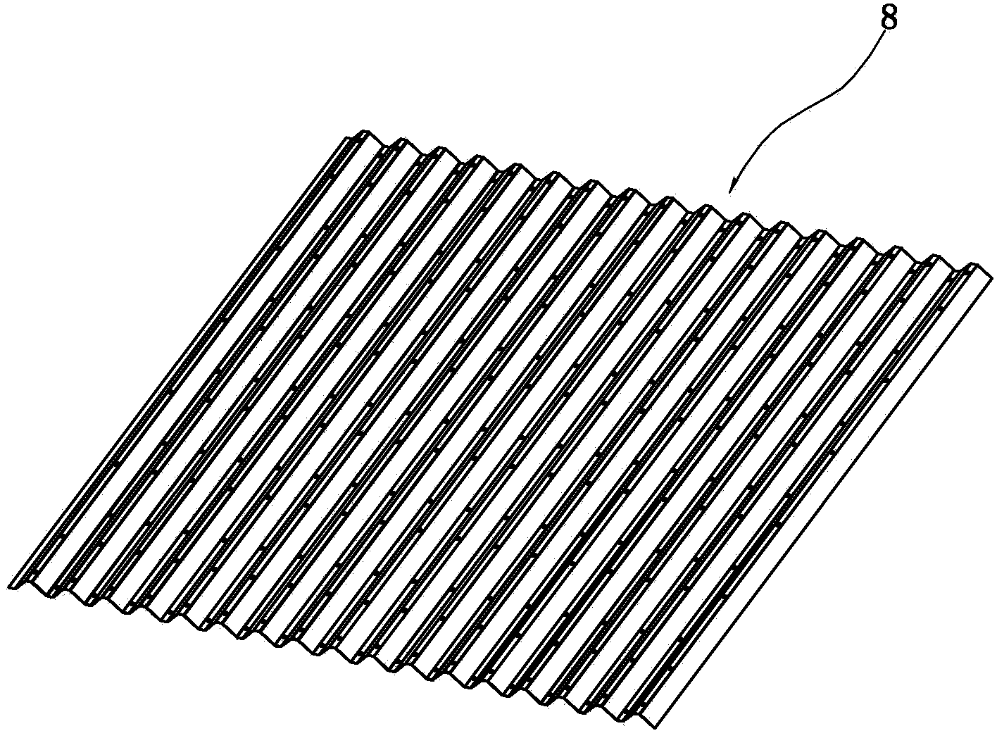
The invention relates to a novel sewage treatment device. The novel sewage treatment device comprises a reaction tank, wherein the reaction tank is separated into an aerobic zone, an anaerobic oxygen-poor zone and an anaerobic zone; the side wall is provided with a water inlet hole and a mud scraper is arranged at the bottom; a mud bucket is arranged below the reaction tank; the mud bucket is internally provided with a pushing device; a separation plate is provided with an aeration device and is accumulated with an AO reactor; a water passing hole and a water passing weir are arranged on the upper part of the reaction tank; a sludge reflowing hole and a liquid supernatant reflowing hole which is connected with a liquid supernatant pumping-out hole of a sedimentation basin are formed in the side wall of the reaction tank; the sedimentation basin and the reaction tank share one side wall; the sludge reflowing hole on the lower part of the sedimentation basin is communicated with the bottom of the sedimentation basin; the sedimentation basin is internally provided with a horizontal flow sediment separation device; a clean water outlet hole is formed in the side wall of the sludge sedimentation basin; the clean water outlet hole is formed above the horizontal flow sediment separation device; a water outlet weir is arranged on the outer side wall of the sedimentation basin. According to the novel sewage treatment device, the plane occupied area is greatly reduced; organic carbon in raw water can be sufficiently utilized to be used as a carbon source needed by a denitrification process of the oxygen-poor zone can be sufficiently utilized so that the adding amount of the additionally-arranged carbon source is reduced and the whole performance of a sewage treatment system is strengthened.

Description

technical field [0001] The invention relates to a novel sewage treatment device. Background technique [0002] With the continuous development of my country's industrial technology and the continuous improvement of people's living standards, the problem of water pollution has also received more and more attention. At present, more than 90% of urban sewage treatment plants in my country cannot meet the national first-class A discharge standard. The key problem is that the relevant indicators of nitrogen cannot meet the standard stably. [0003] At present, the biological nitrogen and phosphorus removal process is widely used in the field of sewage treatment. Among them, the most widely used is the anaerobic-anoxic-aerobic AAO process, and various deformation processes evolved on the basis of it. Arranged in series, that is, to set up sludge return flow and nitrification liquid return flow. Among them, the nitrification liquid return flow is mainly to return the nitrate nitr...

Claims


Application Information

Patent Timeline
IPC IPC(8): C02F3/30
Inventor 俞建德
Owner ZHEJIANG DEAN TECH
Learn More