Greening wall
A green wall and wall technology, applied in the field of green walls, can solve the problems of large storage space for planting media, multiple combined shapes, and high plant coverage, and achieve the effects of improving air quality, increasing greening rate, and controlling haze
- Summary
- Abstract
- Description
- Claims
- Application Information
AI Technical Summary
Benefits of technology
Problems solved by technology
Method used
Image

Examples
Embodiment 1
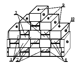
[0027] Example 1: see figure 1, a green wall, including a wall, characterized in that: the wall is only made of or set in the same direction or the same direction by the bottom surface or end surface of a block 1 and is stacked and bonded in a dislocation up and down or along the bottom surface or end surface. Arranged in the same direction or in the same direction and stacked with mortise and tenon connections up and down, the two ends of the upper block 1 overlap part of the top surface of the two blocks 1 adjacent to the lower layer with a certain distance , that is, the top surface of the end of the lower block overlaps the ends of two upper blocks with a certain distance, and the bottom or end of the block 1 is arranged in the same direction or in the same direction and is stacked and bonded in an up and down dislocation or bottom or The end faces are arranged in the same direction or in the same direction and are stacked with mortise and tenon connections to form a hole ...
Embodiment 2
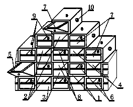
[0036] Example 2: see figure 2 , a green wall, including a wall, characterized in that: the wall is only made of or set in the same direction or the same direction by the bottom surface or end surface of a block 1 and is stacked and bonded in a dislocation up and down or along the bottom surface or end surface. Arranged in the same direction or in the same direction and stacked with mortise and tenon connections up and down, the two ends of the upper block 1 overlap part of the top surface of the two blocks 1 adjacent to the lower layer with a certain distance , that is, the top surface of the end of the lower block overlaps the ends of two upper blocks with a certain distance, and the bottom or end of the block 1 is arranged in the same direction or in the same direction and is stacked and bonded in an up and down dislocation or bottom or The end faces are arranged in the same direction or in the same direction and are stacked with mortise and tenon connections to form a hol...
Embodiment 3
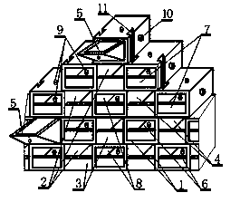
[0050] Embodiment 3: see image 3, a green wall, including a wall, characterized in that: the wall is only made of or set in the same direction or the same direction by the bottom surface or end surface of a block 1 and is stacked and bonded in a dislocation up and down or along the bottom surface or end surface. Arranged in the same direction or in the same direction and stacked with mortise and tenon connections up and down, the two ends of the upper block 1 overlap part of the top surface of the two blocks 1 adjacent to the lower layer with a certain distance , that is, the top surface of the end of the lower block overlaps the ends of two upper blocks with a certain distance, and the bottom or end of the block 1 is arranged in the same direction or in the same direction and is stacked and bonded in an up and down dislocation or bottom or The end faces are arranged in the same direction or in the same direction and are stacked with mortise and tenon connections to form a ho...
PUM
 Abstract
Description
Claims
Application Information
 - R&D Engineer
- R&D Manager
- IP Professional
- Industry Leading Data Capabilities
- Powerful AI technology
- Patent DNA Extraction
Browse by: Latest US Patents, China's latest patents, Technical Efficacy Thesaurus, Application Domain, Technology Topic.
© 2024 PatSnap. All rights reserved.Legal|Privacy policy|Modern Slavery Act Transparency Statement|Sitemap