Turbine blade with leading-edge concaved cavity

A leading edge and blade technology, applied in the direction of blade support components, engine components, machines/engines, etc., can solve the problems of large thermal stress and uneven temperature field of blades, and achieve thermal stress reduction, simple structure, and temperature distribution uniform effect

Inactive Publication Date: 2014-05-21
BEIHANG UNIV +1
View PDF5 Cites 1 Cited by
  • Summary
  • Abstract
  • Description
  • Claims
  • Application Information

AI Technical Summary

Problems solved by technology

However, in order to meet the strength requirements, the turbine blade generally has a relatively thick structure, especially the leading edge of the blade, which directly bears the impact of high-temperature gas, which causes the internal temperature field of the blade to be very uneven and the thermal stress is relatively large.

Method used


Image

  • Turbine blade with leading-edge concaved cavity
  • Turbine blade with leading-edge concaved cavity

Examples


Embodiment Construction

[0008] The present invention will be further described in detail below in conjunction with the accompanying drawings.

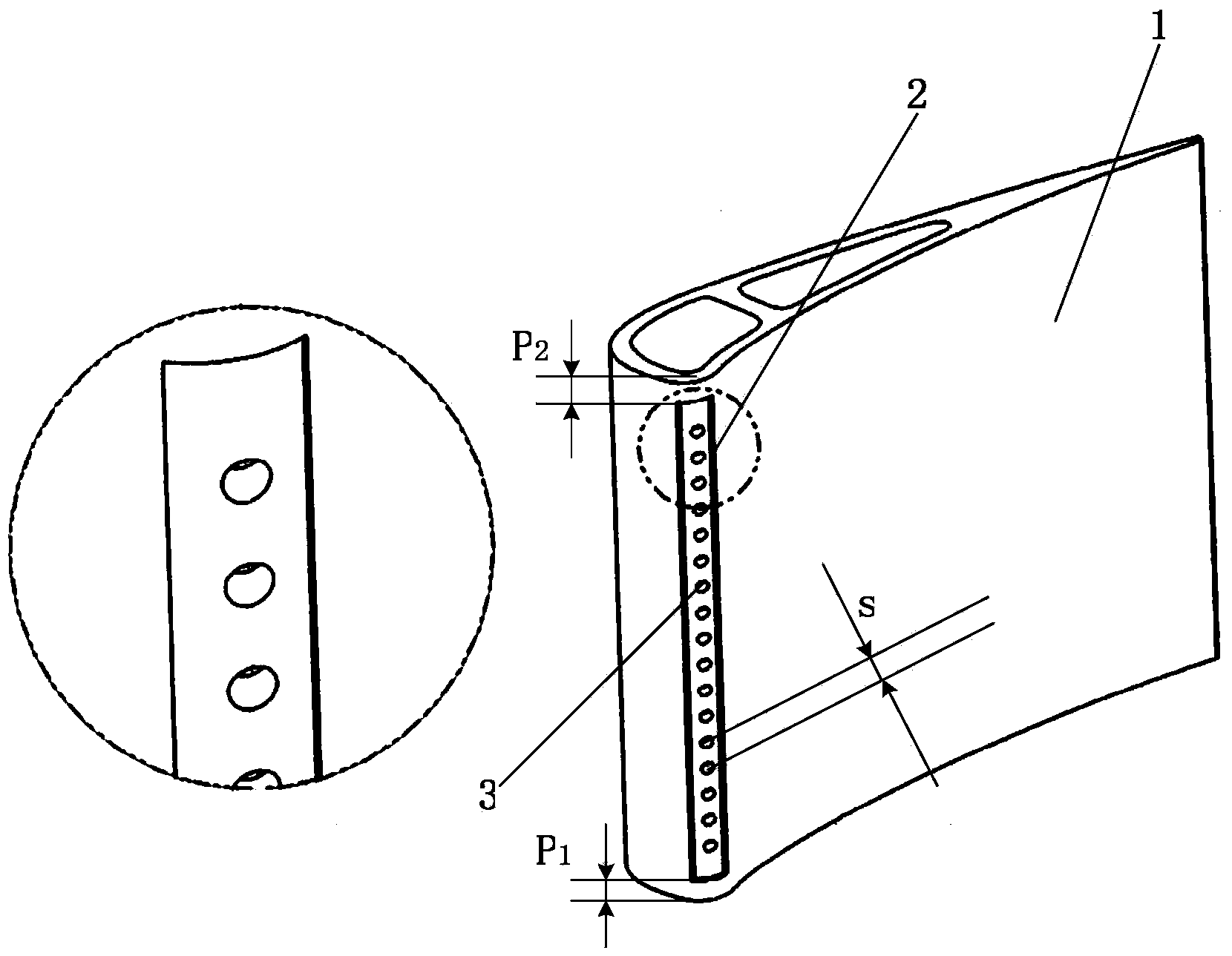
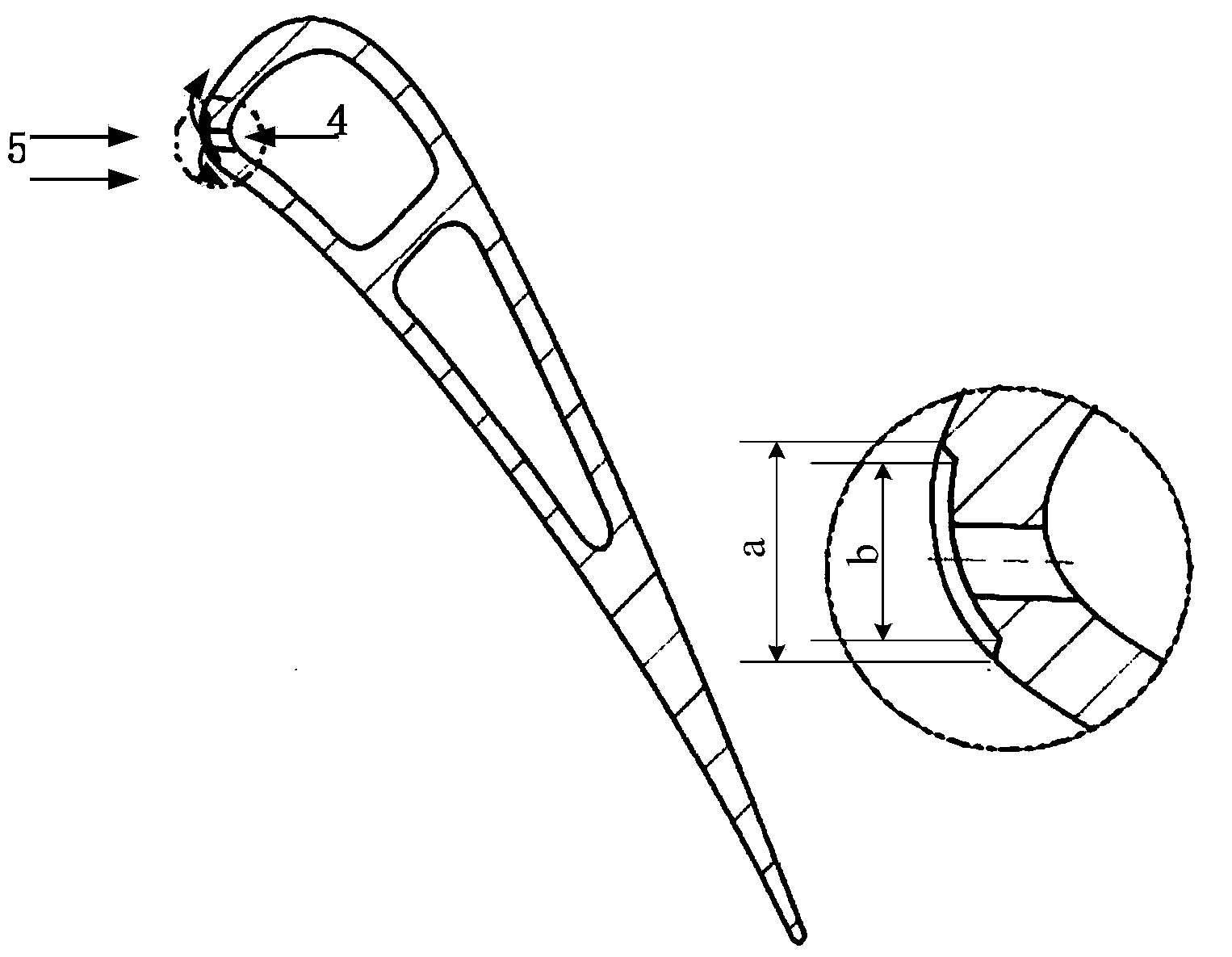
[0009] Such as figure 1 Shown is a schematic diagram of the overall structure of a turbine blade with a leading edge concave cavity structure. The turbine blade includes a blade base (1), a leading edge cavity (2) and an air film hole (3). face, cut a leading edge cavity (2) with a depth of 1 mm to 2 mm inward, and the spanwise width (a) of the opening of the leading edge cavity (2) ranges from 3 mm to 5 mm, forming the bottom surface of the leading edge cavity (2) The profile is the same as that of the original leading edge of the blade. The spanwise width (b) of the bottom surface of the leading edge cavity (2) ranges from 2 mm to 3 mm. The distance between the lower end surface of the leading edge cavity (2) and the blade root (p 1 ) ranges from 6mm to 8mm, the distance between the upper end surface of the leading edge cavity (2) and the tip of the blade...


PUM


Abstract

The invention discloses a turbine blade with a leading-edge concaved cavity. The turbine blade with the leading-edge concaved cavity is suitable for gas turbine engines and comprises a blade base body, the leading-edge concaved cavity and a gas film hole. The turbine blade with the leading-edge concaved cavity is characterized in that a stationary point line is used as a center line by the leading edge of the turbine blade, the molded surface of the leading edge of the blade serves as a reference molded surface, and the concaved cavity with the depth of 1 mm to 2 mm is cut inwards. With the structure of the novel blade, the temperature distribution conditions of the leading edge of the turbine blade can be improved, and the cooling effect can be improved.

Description

technical field [0001] The invention relates to a turbine blade with a leading edge concave cavity structure suitable for a gas turbine engine. The turbine blade has a good cooling effect and aerodynamic performance. Background technique [0002] Turbine blades are one of the most important hot-end components of gas turbine engines. The high-temperature gas generated in the combustion chamber directly impacts on the turbine blades after being rectified and accelerated by the guide vanes. parts. Turbine blade is a special part, which has a large number, complex shape, high requirements, difficult processing, and frequent failure parts. It has always been the key to the production of various engine factories. In order to improve the efficiency of the gas turbine in the aero-engine and increase the thrust-to-weight ratio of the aero-engine, it is necessary to increase the outlet gas temperature of the engine combustion chamber, that is, the inlet temperature before the turbin...

Claims


Application Information

Patent Timeline
Patent Type & Authority Applications(China)
IPC IPC(8): F01D5/18
Inventor 陶智郭文吴宏李育隆苏云亮呼艳丽潘炳华
Owner BEIHANG UNIV
Why Eureka
Try Eureka