
Method and system to control vehicle operation

A level, ambient humidity technology, applied to control devices, vehicle components, transportation and packaging, etc., can solve problems such as coolant leakage

Inactive Publication Date: 2014-05-21
FORD GLOBAL TECH LLC
View PDF5 Cites 1 Cited by
  • Summary
  • Abstract
  • Description
  • Claims
  • Application Information

AI Technical Summary

Problems solved by technology

This corrosion can lead to leaks between the air charge, the atmosphere and in the case of water-to-air coolers the possible coolant

Method used


Image

  • Method and system to control vehicle operation
  • Method and system to control vehicle operation
  • Method and system to control vehicle operation

Examples


Embodiment Construction

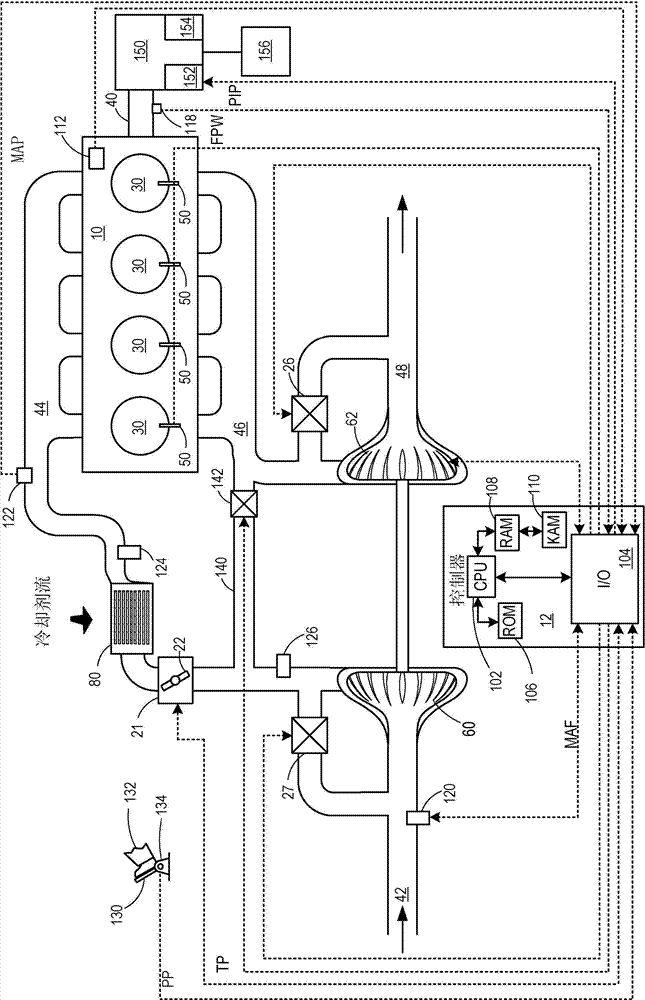
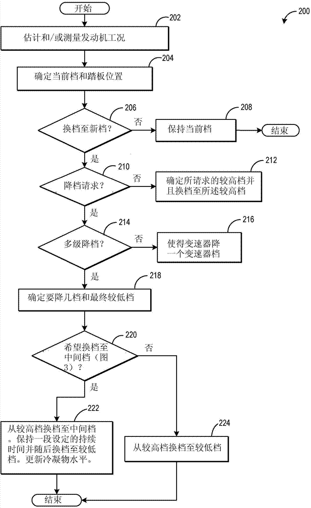
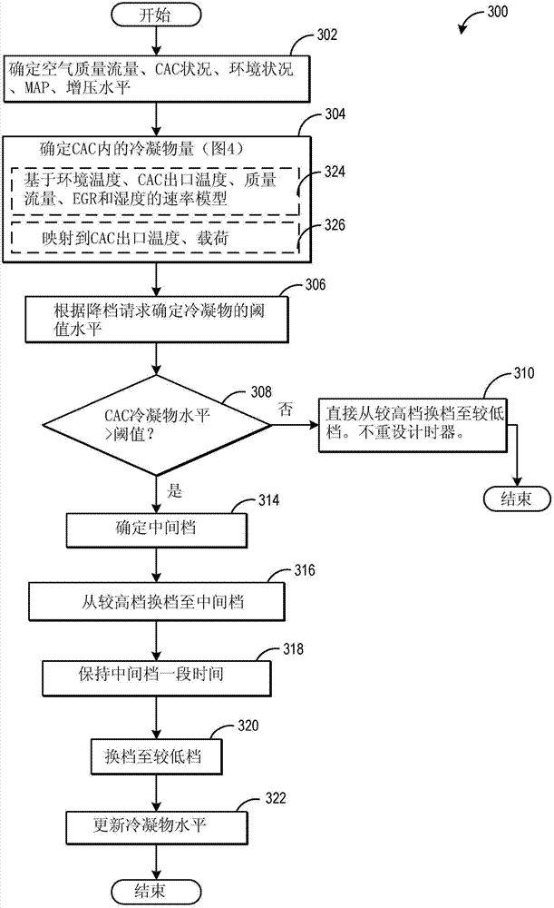
[0028] The following description relates to systems and methods for performing multiple downshifts of transmission gears in an engine system, such as figure 1 system. Shift requests may be generated in response to changes in pedal position. A method for shifting a transmission in response to a changing shift request is disclosed in figure 2 is presented in. In response to a request to shift to a new gear, the transmission may upshift to a higher gear, single gear downshift, or multiple downshifts. Multi-stage downshifts can be performed in stages either directly from higher gears to lower gears or temporarily downshifting to intermediate gears depending on parameters related to condensate release in the charge air cooler. The controller can run control programs such as image 3 A control program to determine whether an intermediate gear can be used based on the condensate level in the CAC. Figure 4 Indicates a method for determining the level of condensate in a CAC. Th...


PUM


Abstract

Methods and systems are provided for performing a multiple gear downshift of a transmission gear by transiently operating in an intermediate gear. In response to ambient humidity and a condensate level in a charge air cooler, the transmission gear may be downshifted from a higher gear to an intermediate gear, and then to a requested lower gear. Downshifting through an intermediate gear may also be controlled based on the gear shift request.

Description

technical field [0001] The present application relates to a method and system for controlling the operation of a vehicle. Background technique [0002] Turbocharged engines use a charge air cooler (CAC) to cool the compressed air coming from the turbocharger before it enters the engine. Ambient air from the outside of the vehicle passes through the CAC to cool the intake air passing inside the CAC. When the ambient air temperature decreases, or during wet or rainy weather conditions, condensation may form within the CAC where the intake air is cooled below the water dew point. When the intake air includes recirculated exhaust gas, the condensate can become acidic and corrode the CAC casing. This corrosion can lead to leaks between the air charge, the atmosphere and, in the case of water-to-air coolers, possibly the coolant. Condensate may accumulate within the CAC and then be drawn into the engine immediately during increased air mass flow, increasing the likelihood of en...

Claims


Application Information

Patent Timeline
IPC IPC(8): F02D29/02F02B29/04
CPCF02D29/02F16H2061/163F16H2061/0444F02B29/0468Y10S477/902F02B29/04F16H61/16Y02T10/12F16H59/60B60W2555/20B60W10/06B60W10/11B60W30/1884B60W30/19F16H59/50F16H61/0204F16H61/04F16H2306/14
Inventor C·P·格鲁格拉S·S·山田
Owner FORD GLOBAL TECH LLC
Learn More