Eureka AIR delivers breakthrough ideas for toughest innovation challenges, trusted by R&D personnel around the world.

Micro-flow continuous adjustment system at high pressure

A regulation system and flow regulation technology, which is applied to components of pumping devices for elastic fluids, liquid variable capacity machinery, pump control, etc., can solve the problem of increasing retention of raw materials, leakage of conveying medium, and increase of medium compression coefficient and other problems, to achieve the effect of convenient and rapid flow adjustment, ensuring system safety and reducing output flow

Inactive Publication Date: 2014-05-21
DALIAN UNIV OF TECH
View PDF7 Cites 0 Cited by
  • Summary
  • Abstract
  • Description
  • Claims
  • Application Information

AI Technical Summary

Problems solved by technology

This solution is simple and feasible, but there are several major defects: (1) The high-pressure buffer tank has high cost, which increases the retention of raw materials, and when the pressure is particularly high, the compression coefficient of the medium increases, and the adjustment ability decreases significantly.
For very high pressure systems, this solution does not meet the safety requirements
(2) The adjustment of pressure and flow requires manual intervention, and the response speed is slow, especially for emergencies such as system outlet blockage, etc., which cannot respond effectively, resulting in continuous increase in pressure, resulting in the opening of the safety valve and leakage of the conveying medium. When the medium is volatile Toxic, flammable, explosive, and corrosive media will cause huge damage. If the safety valve cannot be opened normally, there will be a danger of explosion
(3) The delivery flow rate of the large flow pump is small, causing uneven wear of the plunger and reducing the service life of the pump; when the stroke of the pump is too small, the medium cannot be sucked to achieve effective delivery, that is, the high flow high pressure pump cannot realize the small flow delivery of the medium
Chromatographic pumps or syringe pumps can realize the delivery of small flow and control of pressure, which completely overcomes the above defects, but they are expensive and greatly increase the cost of equipment

Method used


Image

  • Micro-flow continuous adjustment system at high pressure

Examples


Embodiment

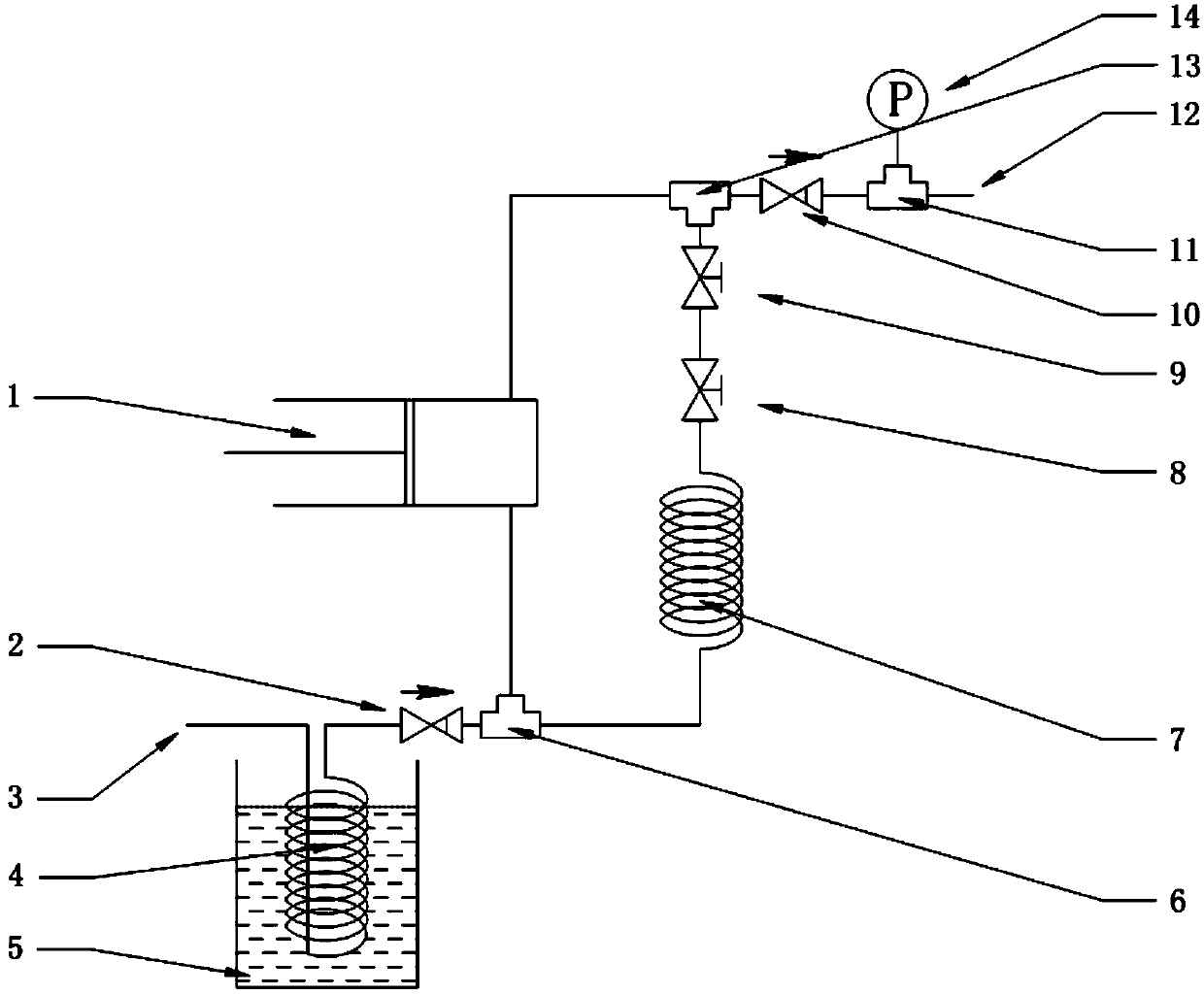
[0017] The cooling system consists of a cooling coil 4 and a low-temperature tank 5; the high-pressure pump delivery system consists of an inlet tee 6, an inlet check valve 2, a high-pressure pump 1, an outlet tee 13, an outlet check valve 10, a pressure gauge tee 11 and The outlet pressure gauge 14 is composed; the flow regulating system is composed of a high-pressure fine-tuning valve 9, a high-pressure fine-tuning metering valve 8 and a flow restrictor 7. For liquefied petroleum gas, carbon dioxide and other media, the upstream 3 of the system is connected to the cooling coil 4 of the cooling structure; for liquid media, the upstream 3 of the system is directly connected to the inlet tee 6 of the high-pressure pump delivery system. The inlet check valve 2 prevents the medium flowing back from the flow restrictor 6 from returning to the upstream 3 of the system. The medium entering from the one-way valve 2 enters the high-pressure pump 1 together with the medium returning fr...


PUM


Abstract

The invention provides a micro-flow continuous adjustment system at the high pressure, and belongs to the field of high-pressure flow delivery. The micro-flow continuous adjustment system comprises a cooling structure, a high-pressure pump delivery structure and a flow adjustment structure. The cooling structure comprises a cooling coil and a low temperature groove, the cooling coil is located in the low temperature groove, the front end of the cooling coil is connected with an external pipe, and the rear end of the cooling coil is connected with one end of an inlet tee joint. The high-pressure pump delivery structure is formed by the inlet tee joint, an inlet one-way valve, a high pressure pump, an outlet tee joint, an outlet one-way valve, a pressure meter tee joint and an outlet pressure meter in a sequentially-connected mode, one end of the inlet tee joint is connected with the rear end of the cooling coil or directly connected with the external pipe, and one end of the pressure meter tee joint is connected with the flow adjustment structure. The flow adjustment structure is formed by a high pressure fine adjustment valve, a high pressure fine adjustment metering valve and a flow limiter in a sequentially-connected mode, the high pressure fine adjustment valve is connected with one end of the outlet tee joint, and the flow limiter is connected with the inlet tee joint in the high-pressure pump delivery structure. The micro-flow continuous adjustment system is simple in structure and low in cost, and has the certain automatic adjustment capacity.

Description

technical field [0001] The invention relates to a micro-flow continuous adjustment system under high pressure, which belongs to the field of high-pressure fluid transportation. Background technique [0002] High-pressure plunger pumps, diaphragm pumps and other high-pressure pumps are widely used in high-pressure and ultra-high-pressure fields such as supercritical technology and liquefied petroleum gas. These high-pressure pumps can adjust the flow accurately by adjusting the stroke, but the flow adjustment range is limited, the stroke of the large flow is too small, the medium cannot be effectively conveyed, and the pressure cannot be directly controlled. In order to achieve flow regulation and ensure system safety, it is often necessary to install a high-pressure buffer tank and a safety valve behind the pump, and it is necessary to manually adjust the stroke or turn off the high-pressure pump to control or stabilize the flow and make the system run safely and stably. Th...

Claims


Application Information

Patent Timeline
Patent Type & Authority Applications(China)
IPC IPC(8): F04B49/22F04B53/08
Inventor 银建中刘一凡徐琴琴喻文徐刚
Owner DALIAN UNIV OF TECH
Why Eureka
Eureka Blog
Learn More