
Water-saving valve core of faucet valve water economizer

A technology of water-saving devices and water-saving valves, which is applied in the field of valves, water-saving devices, spools, faucets, and shower spools, and can solve the problems that restrict the development, popularization, use, and installation of water-saving faucets and other water-saving devices. Convenience, no flooding, etc., to achieve the effect of large room for upgrading and changing functions, simple and scientific structure, and reducing the number of adjustments

Inactive Publication Date: 2014-05-21
梁勇庆
View PDF0 Cites 7 Cited by
  • Summary
  • Abstract
  • Description
  • Claims
  • Application Information

AI Technical Summary

Problems solved by technology

[0003] However, the spools of ordinary faucets and other water-saving devices are still unable to enter thousands of households due to their inherent limitations in structure. Energy-saving, easy to use and install, but high cost and relatively complicated manufacturing, which restricts the development and popularization of water-saving faucets and other water-saving devices
Although saving water is a good thing, once an ordinary water-saving device is installed, it is like a curse, and only small water can be used instead of large water. Do not put water-saving fashion on the water-saving device, and install an ordinary faucet when a large amount of rapid water is needed

Method used


Image

  • Water-saving valve core of faucet valve water economizer
  • Water-saving valve core of faucet valve water economizer
  • Water-saving valve core of faucet valve water economizer

Examples


Embodiment 1

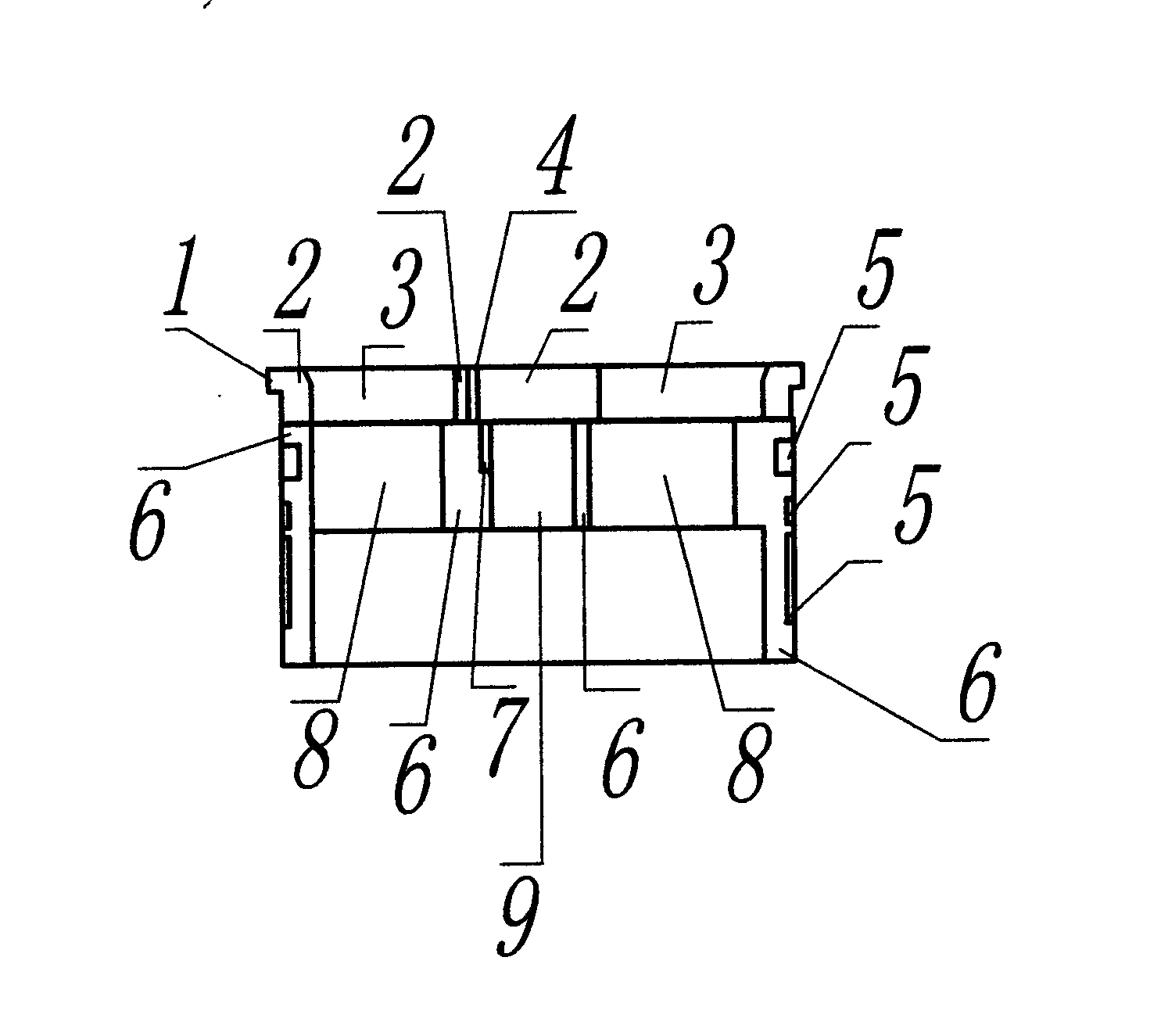
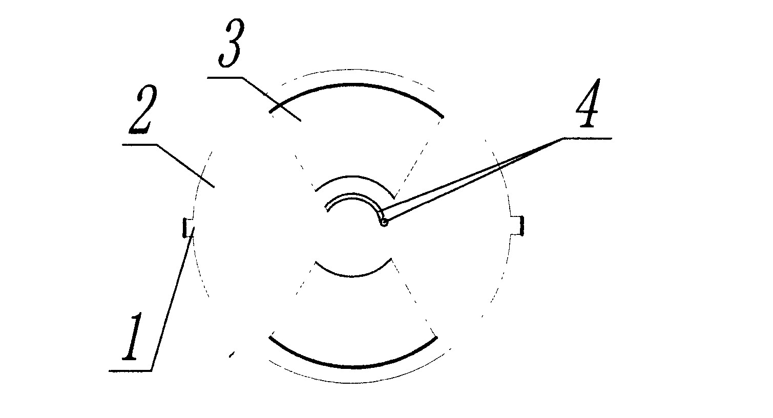
[0033] Embodiment 1 of the present invention: the upper shunt 2 of the water-saving valve core is provided with a bayonet 1, and the bayonet is concave-convex, rib-shaped, hole-shaped, and groove-shaped to match the shell or limit positioning, and the bayonet or concave-convex , Rib shape, card hole, and groove have many forms to match the shell, and the specific position and style of the bayonet (1) depends on the shell (see Figure 13 , Figure 14 , Figure 15 , not exhaustive). In order to better match the shell or according to actual needs, the components in the figure can also be used in combination (such as Figure 13 , Figure 14 , Figure 15 All the upper shunts 2 can be used in this example, but the functions, properties and uses are different). There can be multiple unequal or equidistant teeth, grooves, holes on the groove 5 of wide and narrow size and depth (see attached Figure 4 ), it is also mainly used with the shell to achieve more functions, such as sea...

Embodiment 2

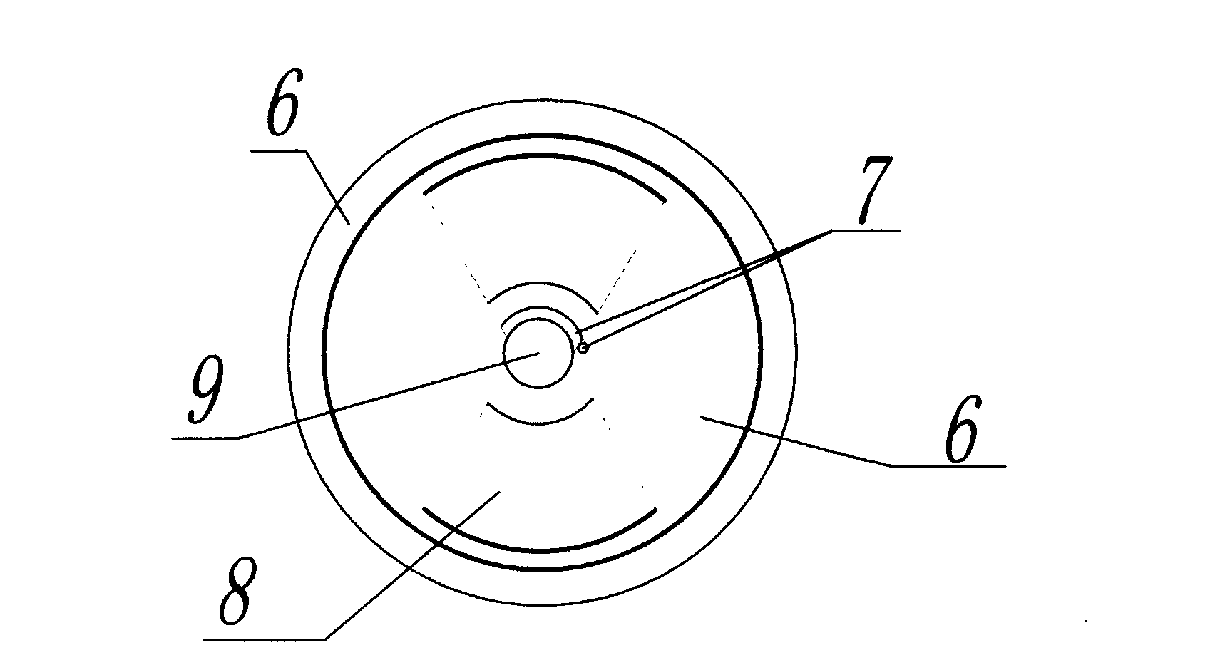
[0035] Embodiment 2: The upper sealing piece 2 of the water-saving valve core is provided with a bayonet 1 bayonet, which is concave-convex, rib-shaped, hole-shaped, and groove-shaped to match the shell or limit positioning, and the bayonet (1) position follows the shell depends. see Figure 13 , Figure 14 , Figure 15 . In order to better match the shell or according to actual needs, the components in the figure can also be used in combination, but the functions, characteristics and purposes are different. The upper shunt hole 3 of the upper shunt sheet 2 cooperates with the lower shunt hole 8 of the lower shunt sheet 6, and the upper and lower shunt sheet holes are all aligned to allow a large amount of water to pass through, and the staggered position of the holes can linearly control the water volume (see Figure 7 , Figure 8 ), to achieve the purpose of adjusting flow. When the upper distribution hole 3 and the lower distribution hole 8 and the upper hole groove 4...

Embodiment 3

[0037] Embodiment 3: Embodiment 3 is a derivative of Embodiment 1 and Embodiment 2. The control process is basically the same, the difference is the upper hole 4 of the upper shunt 2 and the lower hole 7 of the lower shunt 6 . The upper shunt 2 of the water-saving valve core is provided with bayonet 1 to cooperate with the shell or limit positioning. It is concave-convex, rib-shaped, hole-shaped, and groove-shaped. There are many forms for matching the shell. The location depends on the enclosure. Groove 5 is also mainly used for cooperating with the shell. The upper diversion hole 3 of the upper diverter 2 cooperates with the lower diversion hole 8 of the lower diverter 6 to adjust the flow rate, and the lower diversion hole 8 of the lower diverter 6 is completely aligned with the upper diversion hole 3 of the upper diverter 2, so that a large amount of water flows , the size of the staggered position of the holes can linearly control the water volume to achieve the purpose ...


PUM


Abstract

The invention discloses a water-saving valve core of a faucet valve water economizer; the water-saving valve core can be used for linearly adjusting and cutting off, is most water-saving when being used for saving water and is largest in flow than any valve when being used for taking water. The water-saving valve core of the faucet valve water economizer is formed by a movable upper shunting piece and a movable lower shunting piece; the shunting pieces can be sleeved with and connected with selectable accessories in a matching mode; the selectable accessories can be a throttling sprayer or normal energy-saving members or special parts such as a bubbler. The water-saving valve core is simple in structure, scientific, reasonable, easy to manufacture, convenient to mount and use and multifunctional, and can be connected with multiple faucet valves and accessories in the matching mode. The water-saving valve core can be matched with a shell to mark, adjust, lock and control the flow and prevents improper water using, the preset functions and water outlet mode of the water-saving valve core can be limited to prevent a user from randomly changing the functions and purposes of the faucet valve, the water waste phenomenon is reduced, water is greatly saved, and the water-saving valve core is multifunctional and good in adaptivity and can be in a house and fields such as industry, agriculture and public occasions.

Description

technical field [0001] The invention relates to a water-saving device, a valve, a valve core, a faucet, a valve core of a shower, etc., especially a water-saving valve core. It can be extended to be used in industry and agriculture and other occasions that require both switching function and flow rate can be extremely large or small. It can also work in other media and liquids. Background technique [0002] Due to the structure of the spool, the cost, and the process, the current commercially available low-priced faucets and water savers do not have any switch between super-large flow and ultra-low flow until cut-off, especially water-saving devices. As for conventional energy-saving faucets, most of them are in the way of large-caliber water outlets, or they are just a compromise, simply changing the small-caliber or adopting simple methods such as speed-off, foaming to reduce the flow rate, limiting and stopping the flow, or using a throttling nozzle (throttling nozzle). ...

Claims


Application Information

Patent Timeline
Patent Type & Authority Applications(China)
IPC IPC(8): F16K3/08F16K3/30F16K43/00
CPCF16K3/08F16K3/314F16K43/003
Inventor 梁勇庆
Owner 梁勇庆
Learn More