Electric power generation and heating system using solar energy

A heating system and solar energy technology, applied in the direction of solar thermal power generation, solar heating system, heating system, etc., can solve the problem of low heat collection efficiency, and achieve the effect of reducing emissions and use.

Inactive Publication Date: 2014-05-21
全英春 +2
9 Cites 5 Cited by

AI-Extracted Technical Summary

Problems solved by technology

[0004] Since the above-mentioned existing heating systems using solar heat and solar power gener...

Abstract

A the electric power generation and heating system using solar energy according to the present invention comprises a solar cell module configured to convert solar energy into electric energy; a heat collection part formed of a plurality of heat collection rods designed to collect heat from the solar energy; a heat exchange storage tank which is equipped with a heating part which generates heat from the electric energy from the solar cell module and stores fluid as a heat medium oil containing heat collected from the solar heat collection part performs a heat exchange while it flows via a tube; a turbine part into which to receive vapor generated from the fluid stored in the heat exchange storage tank for thereby rotating the turbine; a generator generating electric power as the turbines of the turbine part rotate; a condenser serving to collect and condense the vapor which has been used for rotating the turbines in the turbine part; a heating part which helps heat the building using the fluid condensed by the condenser; a water supply pump which serves to collect the fluid whose temperatures was lowered through the heating procedures by the heating part of the building and transfers the collected fluid to the heat exchange storage tank; and a battery which serves to store the electric power generated by the generator and is electrically connected to the heating part.

Application Domain

Solar heating energyFrom solar energy +10

Technology Topic

Heating systemElectric energy +10

Image

  • Electric power generation and heating system using solar energy
  • Electric power generation and heating system using solar energy
  • Electric power generation and heating system using solar energy

Examples

  • Experimental program(1)

Example Embodiment

[0026] Below, will refer to Figure 2 to Figure 7 The solar power generation and heating system of the present invention will be described.
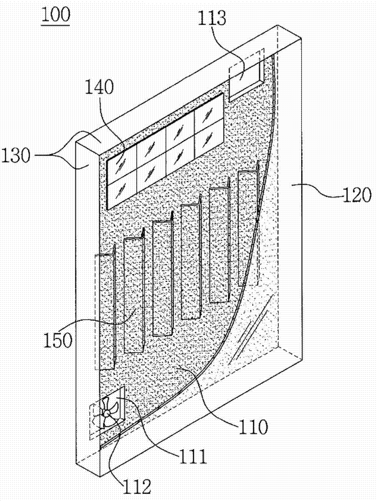
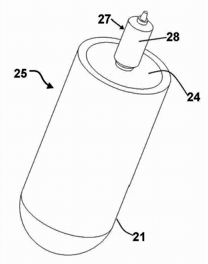
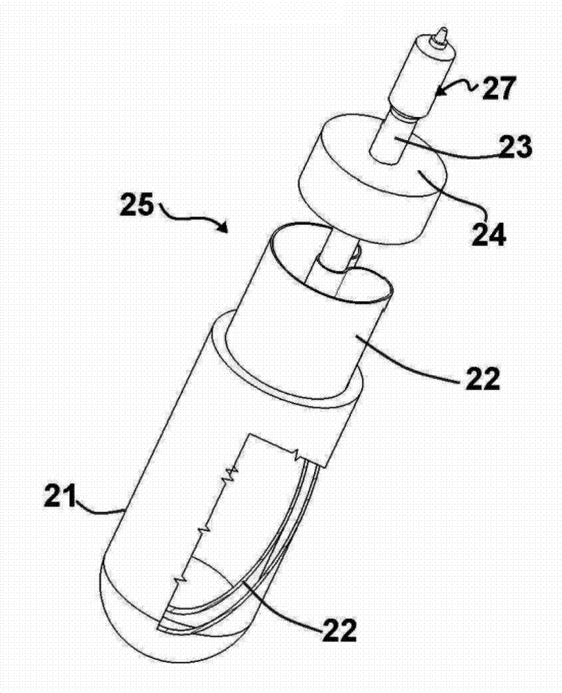
[0027] figure 2 It is the overall structure diagram of the power generation and heating system utilizing solar energy in the present invention. exist figure 2 Among them, the power generation and heating system using solar energy in the present invention includes: a solar cell module 10 that converts solar energy into electrical energy; a heat collecting device 20, which is composed of a plurality of heat collecting rods for collecting heat from the above solar energy; a heat exchange storage box 30, wherein an electric heating body is provided and fluid is stored, the electric heating body conducts heat exchange through the pipeline 37 through which the heat conduction oil flows, and then generates heat through the electric energy output by the solar cell module 10, wherein the above heat conduction oil contains The heat accumulated by the equipment 20; the turbine part 40 rotates the turbine that drives the internal turbine 41 by the inflow of steam generated by the fluid stored in the above-mentioned heat exchange storage tank 30; the generator 50 generates electricity by the rotation of the turbine of the above-mentioned turbine part 40 The condenser 60 recovers and condenses the steam that rotates the turbine in the above-mentioned turbine part 40; the heating part 70 uses the fluid condensed by the condenser 60 to heat the building; The fluid whose temperature drops after being heated by the unit 70 is recovered and supplied to the heat exchange storage tank; the storage battery 90 stores the electric power generated by the above-mentioned generator 50 and conducts conductive connection with the above-mentioned electric heating body. In addition, the electric power generated by the above-mentioned generator 50 is stored in the storage battery 90, which can be used to generate heat for the above-mentioned electric heating body 35, and can also be used to charge the storage battery 90, and the remaining part of the power can also be provided for the building (95). lighting energy.
[0028] image 3 It is a three-dimensional view of the solar heat collecting rod used in the present invention. exist image 3 Among them, the solar heat collector rod 25 used in the present invention includes: a heating rod support shaft 23 inserted and supported on the heat collector rod bracket 22 inserted into the heat collector rod body 21; The envelope 24 for sealing the inside of the rod body 21; the heating rod 27 inserted and arranged at the end of the heating rod support shaft 23 inserted into the envelope 24. The heating rod main body 28 may be in various shapes such as cylindrical, quadrangular or polygonal.
[0029] Figure 4 It is an exploded perspective view of the solar heat collecting rod used in the present invention. exist Figure 4 Among them, the solar heat collector rod 25 used in the present invention includes: a heat collector rod body 21 with a circular bottom surface; a heat collector rod bracket 22 inserted and arranged in the heat collector rod body 21; The heating rod support shaft 23 at the center of the rod bracket 22; insert the above-mentioned heating rod support shaft 23, and the envelope 24 that seals the inside of the heat collecting rod body 21 when connected; Stick 27.
[0030] Figure 5 It is a cross-sectional structural diagram of a solar heat collecting rod used in the present invention. exist Figure 5 Among them, the solar heat collecting rod 25 used in the present invention includes: a space part 29 which is a closed vacuum part formed inside, and a film 29-1 attached and coated with ceramics and carbon inside the space part 29, and The heat collecting rod main body 21 whose bottom surface is sealed; the heat collecting rod bracket 22 inserted and arranged inside the space part 29 formed inside the heat collecting rod main body 21; inserted and arranged in the center of the above heat collecting rod bracket 22, and formed inside The second space part 29-2 is the heating rod support shaft 23 filled with freon gas; the above-mentioned heating rod support shaft 23 is inserted, and the envelope 24 made of asbestos that is arranged on the upper end of the above-mentioned heat collecting rod main body 21 is sealed; and the above-mentioned The heating rod support shaft 23 is connected as a whole, and in order to ensure communication with the inner second space part 29-2 of the above-mentioned heating rod support shaft 23, an inner third space part 29-3 is formed, and the heating rod made of cast iron and silver alloy 27. If the heat collecting rod 25 constituted as above applies solar heat to the heat collecting rod main body 21, the thin film 29-1 coated on one side of the space portion 29 inside the heat collecting rod main body 21 can effectively absorb the solar heat, and make the filling in the heat generating area The Freon gas in the second space 29 - 2 inside the rod support shaft 23 is heated, and the heated Freon gas flows upward and fills the third space 29 - 3 inside the heating rod 27 . The outer surface of the heat collecting rod main body 21 of the heat collecting rod 25 is made of glass, so that sunlight can easily pass through.
[0031] Image 6 It is a cross-sectional composition diagram of the solar heat collecting rod used in the present invention. exist Image 6 Among them, the solar heat collector rod 25 used in the present invention is formed with an airtight space 29 inside the heat collector rod main body 21, and a film 29-1 is attached to one side of the above-mentioned space part 29. On the above-mentioned heat collector rod main body 21 The inner side of the space portion 29 is inserted and provided with a U-shaped heat collecting rod bracket 22 whose two ends form a closed circuit. In addition, a heating rod support shaft 23 is inserted into the center of the heat collecting rod holder 22 and provided.
[0032] Figure 7It is a cross-sectional structural view of the solar heat collection equipment used in the present invention. exist Figure 7 Among them, the solar heat collection equipment 20 used in the present invention includes: a heat collection box 20-3 through which heat transfer oil flows through the inflow port 20-1 and the outflow port 20-2; the heating rod 27 is inserted into the above-mentioned heat collection box 20-3 , the heat collecting rod main body 21 exposes a plurality of heat collecting rods 25 arranged outside the heat collecting box 20-3. The above-mentioned heat conducting oil flows into the heat collecting box 20-3 through the inlet 20-1 of the above-mentioned heat collecting box 20-3, and after being heated by the heat emitted by the heating rod 27 of the above-mentioned heat collecting rod 25, it flows in through the outlet 20-2. Heat exchange storage tank 30. In addition, the above-mentioned heat collecting rod main body is exposed at the bottom of the above-mentioned heat collecting box 20-3. The above-mentioned solar heat energy can be effectively absorbed, and the freon gas filled in the second space portion 29-2 inside the heating rod support shaft 23 inside the above-mentioned heat collecting rod main body 21 can be heated. The freon gas heated as above rises to the third space 29-3 inside the heating rod 27 inside the heat collecting box 20-3, and heats the heat transfer oil flowing in through the inlet 20-1 of the heat collecting box 20-3 . The freon gas whose temperature drops after heating the above-mentioned heat transfer oil is liquefied and descends to the second space part 29-2 inside the main body of the heat collecting rod 25 again, then absorbs solar heat energy again, and repeats the above-mentioned cycle after being heated.
[0033] As mentioned above, the solar power generation and heating system of the present invention can effectively utilize solar energy and minimize energy waste.

PUM

no PUM

Description & Claims & Application Information

We can also present the details of the Description, Claims and Application information to help users get a comprehensive understanding of the technical details of the patent, such as background art, summary of invention, brief description of drawings, description of embodiments, and other original content. On the other hand, users can also determine the specific scope of protection of the technology through the list of claims; as well as understand the changes in the life cycle of the technology with the presentation of the patent timeline. Login to view more.

Similar technology patents

Desulfuration method of clean coal

InactiveCN101831341Areduce usagefast response
Owner:SHANGHAI JIAO TONG UNIV

Low temperature proanthocyanidin extracting process from grape seed

InactiveCN1506361Alow costreduce usage
Owner:沈阳中科药业有限责任公司

Continuous membrane filtration system and water treatment method

ActiveCN103288177Areduce usagelow cost
Owner:ZHEJIANG JINMO ENVIRONMENT TECH CO LTD

Touch display module

Owner:金龙机电(杭州)有限公司

Classification and recommendation of technical efficacy words

  • reduce usage
  • emission reduction

Chitosan oligosaccharide compounded preparation and application in prolonging shelf life of fruits

InactiveCN104642528AExtend fruit shelf lifereduce usage
Owner:DALIAN INST OF CHEM PHYSICS CHINESE ACAD OF SCI

Fish-vegetable symbiotic integration system

InactiveCN103999812Areduce usageSave on bait usage
Owner:姜威毅

Full-color 3D printing device and method

ActiveCN106393662Awide color gamutreduce usage
Owner:SHENZHEN 7TH TECH CO LTD

Medical washing and disinfecting machine

InactiveCN104826144Areduce usageImprove efficiency
Owner:广州涞泊锐科技股份有限公司

Temperature-sensitive color-changing coating

InactiveCN102585674Amaintain a comfortable temperaturereduce usage
Owner:武汉康桥伟业高新科技有限公司

Water treatment method for cyclic purification of shrimp breeding wastewater

ActiveCN104445834Aemission reductionReduce the pressure on the ecological environment
Owner:海南禄泰海洋生物科技有限公司
Why Eureka
Try Eureka