A leak detection detection head, condenser online leak detection device and its application

A detection head and condenser technology, applied in the field of leak detection detection head, can solve the problems of low efficiency, low detection efficiency, cumbersome operation, etc., and achieve the effects of reducing maintenance costs, prolonging operating hours, and improving production efficiency

Active Publication Date: 2016-08-31
NANJING SCIYON AUTOMATION GRP +1
View PDF6 Cites 0 Cited by
  • Summary
  • Abstract
  • Description
  • Claims
  • Application Information

AI Technical Summary

Problems solved by technology

Including positive pressure method and negative pressure method, usually using shutdown detection, need to pressurize the condensing chamber of the condenser, also use vacuum, or pressurize the condensing pipe after closing the condensing pipe under test, etc. These methods are all It requires external power, and then manually checks the pressure or air flow of the condenser tubes one by one, which is inefficient
At present, there is also a pressure detection method under the condition of semi-shutdown. This method is to stop the work of the water chamber where the condensing pipe to be tested is located, and the other part of the condensing pipe is still working to generate a vacuum in the condenser. Although the semi-shutdown method does not require additional power, but it is still manual to detect the pressure or airflow of each condensing tube to be tested to judge the leak point
Although these pressure detection methods can effectively detect leak points, they are all manually detected under shutdown or semi-stop conditions. Most of them require external power, the operation is cumbersome, and the detection efficiency is low.

Method used


Image

  • A leak detection detection head, condenser online leak detection device and its application
  • A leak detection detection head, condenser online leak detection device and its application
  • A leak detection detection head, condenser online leak detection device and its application

Examples


Embodiment Construction

[0038] The present invention will be described in detail below in conjunction with the accompanying drawings.

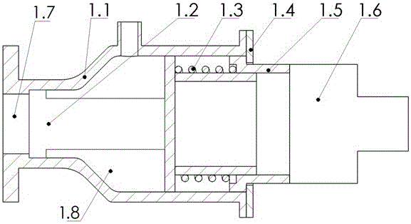
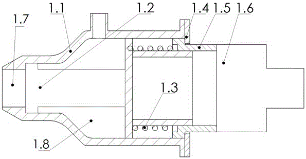
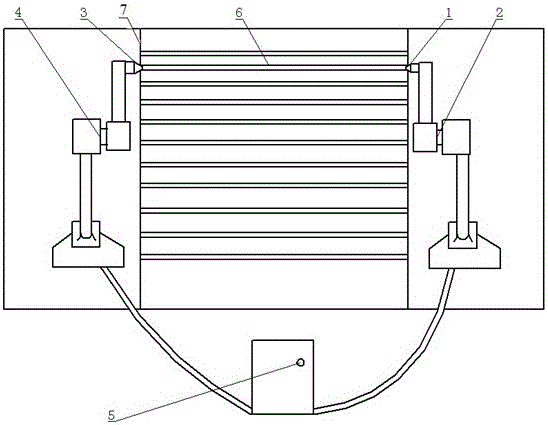
[0039] like Figure 4As shown, the online condenser leak detection device of the present invention includes: a leak detection probe 1 , a first mechanical arm 2 , a plugging device 3 , a second mechanical arm 4 and a control system 5 . Among them, the mechanical arm 1 2 and the mechanical arm 2 4 are respectively installed in the two water chambers of the condenser, and the dual-degree-of-freedom mechanical arms can move along the area parallel to the tube sheet 7 plane of the condenser. The leak detection probe 1 and the plugging device 3 are installed on the first mechanical arm 2 and the second mechanical arm 4 respectively. The control system 5 adopts a PLC control system or a DCS of a power plant, and connects the first mechanical arm 2, the second mechanical arm 4, the leak detection probe 1 and the plugging device 3 through control lines.

[0040] The leak d...


PUM


Abstract

The invention discloses a leakage detecting head, a condenser on-line leakage detecting device with the leakage detecting head and a leakage detecting method. The leakage detecting head is used for detecting leakage of a condenser condensation tube and comprises a casing, a pressure sensor and a driving device, wherein the front end of the casing is open, the pressure sensor is arranged in the casing and connected with the casing in a sealing mode, the inside of the casing is divided into front and rear cavities such as a pressure detecting cavity and a pressure stabilizing cavity, the driving device is connected with the rear end of the casing, and when leakage detection is performed, the front end of the casing is in sealing fit with tube plates on the periphery of the condensation tube to be detected, or the front end of the casing stretches into the condensation tube to be detected to be in sealing fit with the inner wall of the condensation tube. The condenser on-line leakage detecting device comprises the leakage detecting head, a choke plug, a mechanical arm and a control system. By means of the leakage detecting head and the condenser on-line leakage detecting device, the automation of the on-line leakage detecting process can be effectively achieved, and the usage is convenient and fast, and safe and reliable.

Description

technical field [0001] The invention relates to a leak detection probe for on-line leak detection of a condenser, a leak detection device using the leak detection probe and a specific leak detection method. Background technique [0002] The condenser is an important device in the steam turbine power generation system of a thermal power plant. Its main function is not only to condense the exhaust steam of the steam turbine into water for reuse by the boiler, but also to establish and maintain a vacuum at the exhaust steam of the steam turbine. The efficiency of the steam turbine has a great relationship with the vacuum degree of the condenser, the greater the vacuum degree, the higher the efficiency. Once the condenser leaks, the vacuum will drop. The leakage of the condenser mostly occurs in the condenser tube or the junction of the condenser tube and the tube sheet. However, there are a large number of condenser tubes in the condenser, and leak detection is a difficult pro...

Claims


Application Information

Patent Timeline
Patent Type & Authority Patents(China)
IPC IPC(8): G01M3/28
Inventor 沈德明刘国耀贺赟晖
Owner NANJING SCIYON AUTOMATION GRP
Why Eureka
Try Eureka