Data processing method based on servo drive unit

A servo drive unit and data processing technology, applied in the direction of digital variable display, etc., can solve problems such as difficult to display low repetition rate signals, low electrical signals, difficult to display frequency, etc., and achieve friendly graphical human-computer interaction interface, plug-in Ready-to-use, accurate data collection effect

Active Publication Date: 2014-05-21
SHENYANG GOLDING NC & INTELLIGENCE TECH CO LTD
View PDF6 Cites 6 Cited by
  • Summary
  • Abstract
  • Description
  • Claims
  • Application Information

AI Technical Summary

Problems solved by technology

Since the servo drive unit transmits analog signals or pulse signals, when using an oscilloscope for parameter setting and adjustment, you can only use the rotary button on the oscilloscope for fine-tuning, so you cannot quickly and accurately set and adjust the parameter values ​​of the servo drive unit. Adjustment
Oscilloscopes are not only complicated to use, but professional CNC technicians who can use oscilloscopes are required, and oscilloscopes have the following disadvantages. First, because the afterglow time of CRT is very short, it is difficult to display electrical signals with very low frequencies; The brightness of the scanning spot is inversely proportional to the scanning speed, so it is difficult to display a signal with a low repetition rate with a fast rise and fall time; again, the oscilloscope is bulky and expensive, and the amount of data transmitted by the servo drive unit based on analog and pulse interfaces The characteristics of less and one-way communication determine that one oscilloscope cannot be used to debug multiple servo drive units at the same time in the servo drive unit, and the oscilloscope does not have the function of data storage, which undoubtedly increases the user's cost
[0003] In summary, the traditional oscilloscope debugging method based on analog quantities in the servo drive unit is not only inefficient, inflexible, and difficult to operate, but also not conducive to the on-site debugging and testing of the servo drive unit, and cannot meet the needs of the development of the CNC system

Method used


Image

  • Data processing method based on servo drive unit
  • Data processing method based on servo drive unit
  • Data processing method based on servo drive unit

Examples


Embodiment Construction

[0040] The present invention will be further described in detail below in conjunction with the accompanying drawings and embodiments.

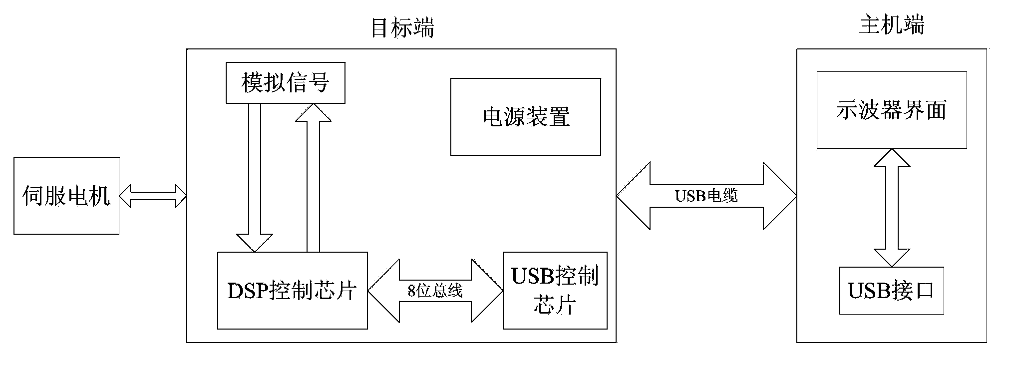
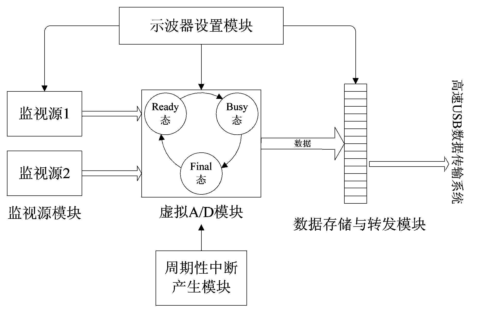
[0041]The technical scheme of the present invention is: directly on the internal DSP chip TMS320F28335 of the servo drive unit, a virtual A / D module is pushed, and the virtual module is driven by a periodic interruption of a fixed frequency, and the data to be observed is collected under the effect of the interruption. It can be an actual physical quantity, such as the A-phase current of the motor, or it can be a result calculated by a motor control algorithm at that moment by the servo drive unit. Then the collected data is stored in the FIFO queue, and the data in the FIFO is sent to the PC through the high-speed USB interface chip PDIUSBD12, and finally the relevant data is reconstructed by the PC into time-domain waveform images and spectrograms to calculate the data Peak time, overshoot, and steady-state error are displayed on the PC-side...


PUM


Abstract

The invention relates to a data processing method based on a servo drive unit. The method comprises the following steps: a DSP chip in the servo drive unit receives and initializes sampling information from a host side; a virtual A/D module in the DSP chip samples input servo motor feedback data and control input data according to periodic interrupt generated by a timer inside the DSP chip, and sends the sampled data to the host side through a FIFO; and the host side processes a received data frame, and displays time-domain and frequency-domain waveforms and control adjustment parameters of servo motor operation. The method enables the servo drive unit to be debugged more conveniently, more flexibly and more efficiently; the method has the following advantages: acquired data is accurate, the data precision is high, algorithm data is directly acquired, the method is embedded into the servo drive unit, and the like; and the method further has the following advantages: a friendly graphical man-machine interaction interface is provided, internal data of the servo drive unit is displayed in real time, and any detail part of an image can be magnified without being limited by offset of a zero-point coordinate axis.

Description

technical field [0001] The invention relates to an AC servo drive unit, in particular to a data processing method capable of displaying internal data waveforms of the servo drive unit. Background technique [0002] High-performance servo drive unit is of great significance to CNC machine tools, which directly affects the machining accuracy and speed of CNC machine tools. To optimize the performance of the servo drive unit, it is necessary to set appropriate control parameters for the servo drive unit. Since the servo drive unit transmits analog signals or pulse signals, when using an oscilloscope for parameter setting and adjustment, you can only use the rotary button on the oscilloscope for fine-tuning, so you cannot quickly and accurately set and adjust the parameter values ​​of the servo drive unit. Adjustment. Oscilloscopes are not only complicated to use, but professional CNC technicians who can use oscilloscopes are required, and oscilloscopes have the following disa...

Claims


Application Information

Patent Timeline
Patent Type & Authority Applications(China)
IPC IPC(8): G01R13/02
Inventor 王泽鹏杜桂红陈猛于菲王志成袁田
Owner SHENYANG GOLDING NC & INTELLIGENCE TECH CO LTD
Why Eureka
Try Eureka