Low-energy electron beam device

An electron beam device and low-energy technology, applied in the field of low-energy electron beam devices, can solve the problems of easy to be seriously offset, difficult to obtain and measure large dynamics, output parallel beams, etc., and achieve the goal of improving repeatability and operability Effect

Inactive Publication Date: 2014-05-21
北京高能科迪科技有限公司
View PDF2 Cites 1 Cited by
  • Summary
  • Abstract
  • Description
  • Claims
  • Application Information

AI Technical Summary

Problems solved by technology

Existing low-energy electron beam devices, because the extremely low-energy electron beam is prone to be seriously deflected by interference such as geomagnetism, it is difficult to output parallel beams at various energies, and it is difficult to obtain and measure extremely small electron beam currents with a large dynamic range

Method used


Image

  • Low-energy electron beam device

Examples


Embodiment Construction

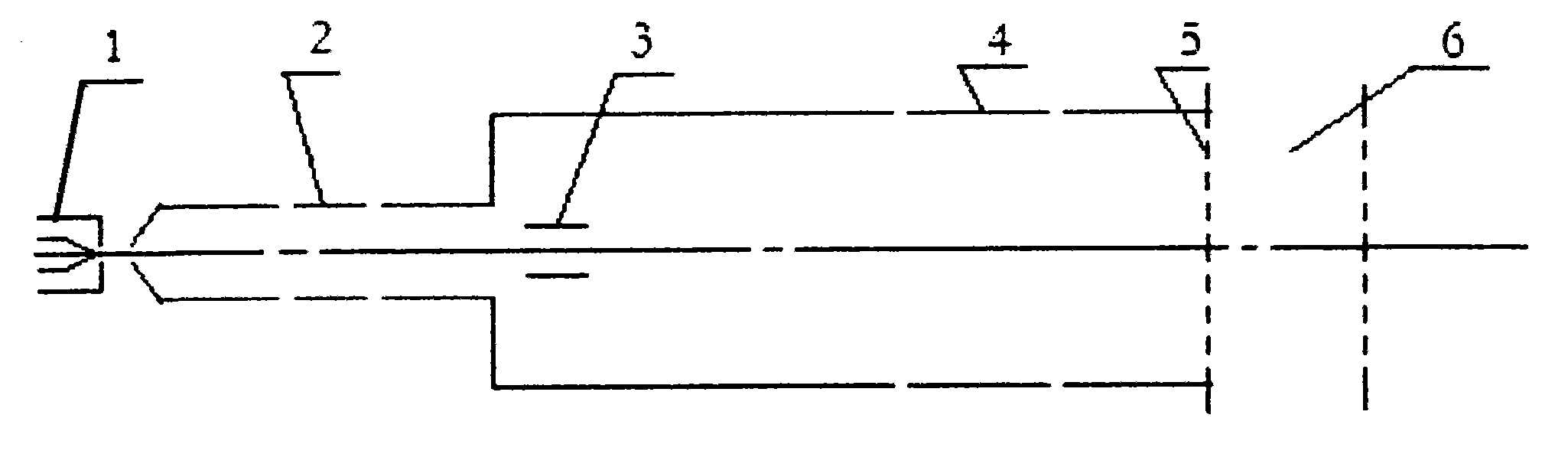
[0011] Such as figure 1 As shown, the low-energy electron beam device of the present invention includes an electron gun 1, a first unipotential lens 2, a second unipotential lens 4, and two grids 5 arranged in sequence with grids and extraction electrodes; two grids 5 A deceleration gap 6 is formed between them; two pairs of guide deflection plates 3 are arranged between the first and second single potential lenses, the first single potential lens is focused and imaged between the two pairs of deflection plates, and the second single potential lens The focal point of 4 is located at this imaging place.

[0012] Both the first unipotential lens 2 and the second unipotential lens 4 are three-cylindrical decelerating (or accelerating) unipotential lenses.

[0013] The advantages of the low-energy electron beam device of the present invention are as follows:

[0014] The energy range of the low-energy electron beam device described in this patent is 0.02-200keV, and the beam cur...


PUM


Abstract

The invention provides an adjustable minimal-beam electron beam device which has the advantages of simple structure, convenient operation, ultra-low energy, large area, small divergence angle and large dynamic range. The device comprises an electron gun with a grid electrode and a leading-out electrode, a first univoltage lens, a second univoltage lens and two grid meshes arranged in sequence, wherein a deceleration gap is formed between the two grid meshes; guide deflectors are arranged between the first univoltage lens and the second univoltage lens; the first univoltage lens is focused and imaged between the two pairs of deflectors; and the focus of the second univoltage lens is located at the imaging place. According to the low-energy electron beam device, the beams constantly maintain in a high-energy state during the flying process, severe deviation and various quadratic effect?influences of the ultra-low energy beam under the interference of an external magnetic field can be avoided; and in addition, when the energy is changed, parallel beams are always outputted only by adjusting the energy value, the adjustment is simple and convenient, and the repeatability and maneuverability of the device are greatly improved.

Description

technical field [0001] The invention relates to an accelerator, especially a low-energy electron beam device. Background technique [0002] Particle detectors used on aircraft need to be calibrated before flight in space research. Calibration requires standard particle sources of various energies. Very low energy electron beams are commonly used particle sources. The requirement for this device is to output an electron beam with adjustable energy, large diameter, large dynamic range, small beam current, and small divergence angle. Existing low-energy electron beam devices, because the extremely low-energy electron beam is prone to be seriously deflected by interference such as geomagnetism, it is difficult to output parallel beams at various energies, and it is difficult to obtain and measure extremely small electron beam currents with a large dynamic range . Contents of the invention [0003] The invention provides a low-energy electron beam device with simple structu...

Claims


Application Information

Patent Timeline
Patent Type & Authority Applications(China)
IPC IPC(8): H01J33/00
Inventor 张华顺赵涛
Owner 北京高能科迪科技有限公司
Why Eureka
Try Eureka