
Self-synchronizing trigger high capacity discharging gap

A technology of discharge gap and trigger gap, which is applied in the field of self-synchronized triggering of large-capacity discharge gap, can solve the problems of increasing the complexity of the control system and power pulse system, increasing the cost of the gap and related auxiliary equipment, and reducing the reliability of the gap action. Basically stable operating characteristics, reduced device cost and complexity, and improved device reliability

Inactive Publication Date: 2014-05-21
李品德 +1
View PDF6 Cites 3 Cited by
  • Summary
  • Abstract
  • Description
  • Claims
  • Application Information

AI Technical Summary

Problems solved by technology

The disadvantage of this principle is: the moment of "ignition" of the trigger electrode must be synchronized with the phase of the peak voltage of the main discharge gap, otherwise the main discharge gap will not break down even if there is "ignition", that is, there is a control dead zone, which is to a large extent This increases the complexity of the control system and the power pulse system, reduces the reliability of the gap action, and increases the cost of the gap and related ancillary equipment.
In addition, some controllable gaps place the trigger electrode within one electrode of the main electrode. The trigger electrode is easily affected by metal vapor or electrode ablation when the main electrode is discharged, which will change the trigger characteristics, resulting in a decrease in control stability.
[0004] At present, there are no designs, patents or products of self-synchronizing discharge gaps at home and abroad that have the characteristics of large capacity, high stability and high reliability, self-triggering and no control dead zone, reusable, simple structure, convenient control, and low cost.

Method used


Image

  • Self-synchronizing trigger high capacity discharging gap
  • Self-synchronizing trigger high capacity discharging gap
  • Self-synchronizing trigger high capacity discharging gap

Examples


Embodiment Construction

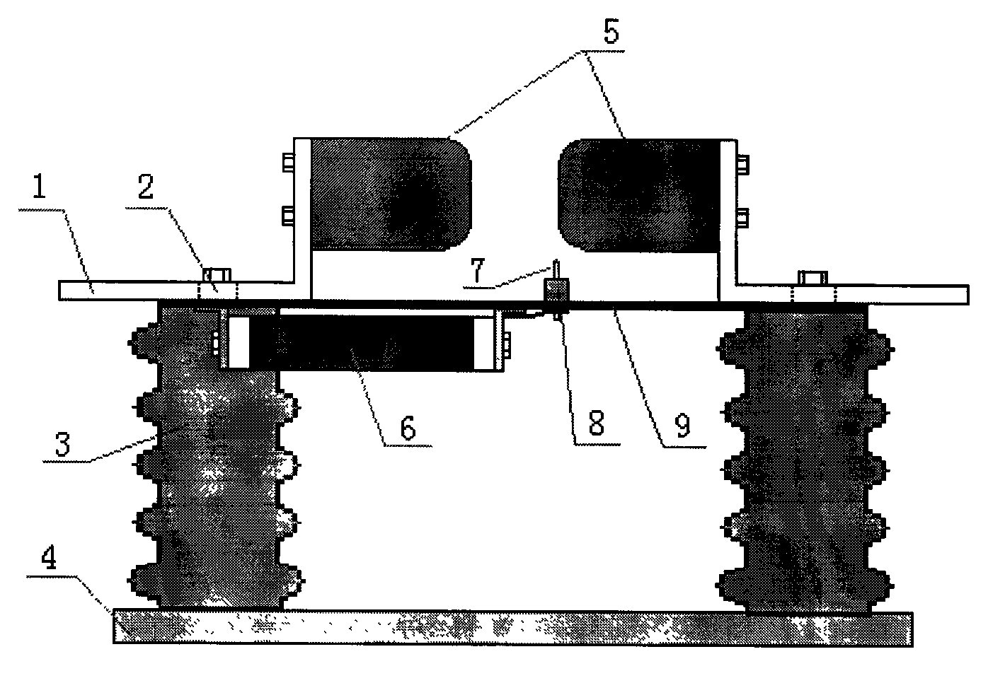
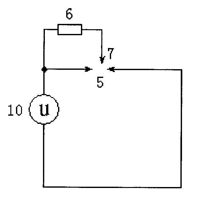
[0013] figure 1 It is a structural schematic diagram of the present invention, the main discharge electrode 5 is installed on the conductive row 1, connected and fixed with the support insulator 3 through the long slot 2, and the support insulator is fixed on the base 4, and the above long slot is used to adjust the distance of the main discharge gap . The arc-resistant insulating plate 9 is overlapped between the two insulators, the impedance device 6, the trigger electrode 7 and the electrode seat 8 are fixed on the arc-resistant insulating plate 9, and the position and distance of the trigger electrode can be adjusted through the electrode seat 8. figure 2 The device 10 in represents the voltage applied across the main discharge gap. Since the distance between the main discharge gap and the trigger gap can be adjusted separately, the protection characteristics of the discharge gap can be artificially changed according to the needs of the application. At the same time, si...


PUM


Abstract

The invention relates to a self-synchronizing trigger high capacity discharging gap applied to a high voltage system; an impedance device 6 synchronously tracks voltage at two ends of a main discharging gap 5, the main discharging gap is instantaneously broken down by plasmas, free electrons and ultraviolet light generated through the pre-discharging of a triggering gap 7 serially connected with the impedance device under the set voltage, and thus the purpose of rapid connection of a circuit or over voltage protection is achieved. The self-synchronizing trigger high capacity discharging gap has the positive effects that: 1, the voltage at two ends of a triggering electrode is taken from the autonomous discharging gap, extra triggering control systems are not required, the cost and complexity of the device are greatly reduced, and the device reliability is enhanced; 2, the triggering gap is positioned at an arc blind area of the main discharging gap, the triggering operation voltage is not changed due to arc ablation of the main discharging gap, so that the device can be used for many times, and the basic stabilization of operation characteristic can be maintained; 3, the distances of the main discharging gap and the triggering gap are convenient to adjust, and requirements for different protection characteristics can be satisfied.

Description

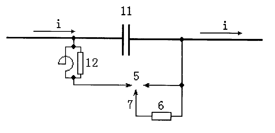
technical field [0001] The invention relates to a self-synchronous trigger large-capacity discharge gap, which belongs to the field of electrical components and is mainly used for high-current trigger conduction, high-current bypass or overvoltage protection of AC or DC high-voltage circuits in power systems. Background technique [0002] In the AC or DC high-voltage circuit of the power system, it is often necessary to trigger conduction with a large current or fast over-voltage protection including power frequency over-voltage. A typical requirement is the overvoltage protection of the capacitor series compensation device in the power system. This kind of protection belongs to the power frequency overvoltage protection and requires the discharge gap to have the characteristics of large capacity, high stability and reusability; especially at 7.2kV~40.5 The kV distribution voltage level also requires the discharge gap to have the characteristics of simple structure, convenie...

Claims


Application Information

Patent Timeline
IPC IPC(8): H01T2/02
Inventor 李品德李梦菲
Owner 李品德
Learn More