
Signal measurement device and signal measurement method

A technology for signal measurement and signal quality, applied in pilot signal distribution, wireless communication, signaling distribution, etc., to achieve the effect of improving accuracy

Inactive Publication Date: 2014-05-21
HITACHI LTD
View PDF13 Cites 12 Cited by
  • Summary
  • Abstract
  • Description
  • Claims
  • Application Information

AI Technical Summary

Problems solved by technology

It is possible that the signal quality Q actually used for data transmission of the macro base station TP6 N s , so the UE gets a worse service than the original serving cell, and this handover is unnecessary for the UE

Method used


Image

  • Signal measurement device and signal measurement method
  • Signal measurement device and signal measurement method
  • Signal measurement device and signal measurement method

Examples


no. 1 approach

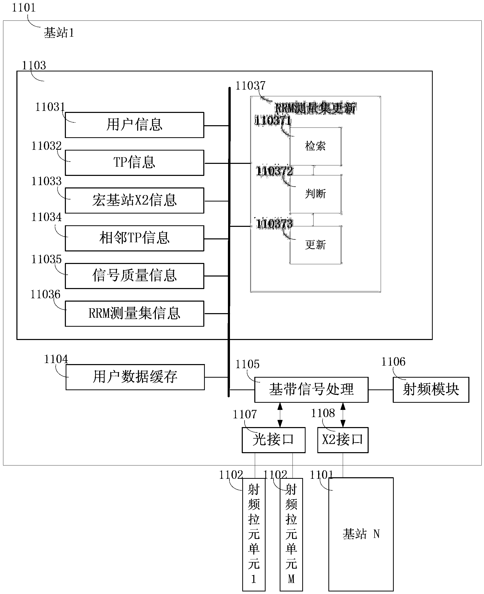
[0055] figure 1 It is a schematic diagram of the internal structure of a macro base station (macro TP) in a heterogeneous network composed of macro nodes and micro nodes related to the first embodiment. The components related to the update of the RRM measurement set are mainly shown.

[0056] in, figure 1 The reference numeral 1101 in the above indicates macro base stations (base stations) 1-N (Macro eNB, macro TP) in a certain scene in the heterogeneous network. Each macro base station 1-N can be connected to other macro base stations through the X2 interface 1108 . The X2 interface 1108 is a standard interface between base stations.

[0057] In addition, each macro base station 1-N is also connected to each micro-node under it through an optical interface 1107, and the optical interface 1107 is an interface between micro-nodes included in the respective ranges of base stations 1-N. exist figure 1 The micro node in the middle is a radio frequency pull unit (RRH, micro...

no. 2 approach

[0108] In addition to the RRM measurement set update process described in the first embodiment, the signal measurement device of the present invention can also expand various services based on the update of the RRM measurement set, so as to realize diversified services based on scene judgment.

[0109] Figure 10 It is a schematic diagram of the internal structure of a macro base station (macro TP) in the heterogeneous network according to the second embodiment.

[0110] Compared with the first embodiment, the macro base station (macro TP) in the second embodiment is different in that in addition to the constituent units related to the RRM measurement set update, it also has other expansions based on the RRM measurement set update results Constituent units of business are described here with emphasis on points that are different from those in the first embodiment, and for points that are the same as those in the first embodiment, the above descriptions in the first embodiment ...


PUM


Abstract

The invention aims at providing a signal measurement device capable of achieving mobility measurement in a heterogeneous network formed by macro nodes and micro nodes and improving the signal measurement accuracy in the mobility measurement. The signal measurement device is used for signal measurement in the heterogeneous network formed by the macro nodes and the micro nodes. The signal measurement device is characterized by comprising a retrieval module for retrieving scene information of adjacent nodes adjacent to a terminal device in a database, a judgment module for judging whether the adjacent nodes belong to a scene where multiple nodes are provided with the same cell identifiers, and an updating module, wherein the scene information comprises, at least, a node structure in a scene where the adjacent nodes are located and node identifier information, and the updating module is used for updating a radio resource management set based on a cell specific reference signal (CRS) when a judgment result of the judgment module is no, and updating the radio resource management set based on a channel state information reference signal (CRS-RS) when the judgment result of the judgment module is yes.

Description

technical field [0001] The present invention relates to devices and methods for providing services in a mobile communication network. In particular, it relates to a signal measurement device and a signal measurement method used in a mobile communication heterogeneous network in a multi-base station joint service system. The mobile communication network mentioned here is a mobile communication system that supports joint service of multiple base stations. Background technique [0002] At present, with the increase of mobile users and the high demand for data rate, the traditional cellular network is increasingly unable to meet the needs of the majority of users. The 3rd-Generation Partnership Project (The 3rd-Generation Partnership Project) is an international standard organization that has developed system architectures and standards for second-generation and third-generation mobile communication networks. These standards have been applied to the network that has already de...

Claims


Application Information

Patent Timeline
Patent Type & Authority Applications(China)
IPC IPC(8): H04W24/08H04B7/06
CPCH04L5/0035H04L5/005H04L5/0057H04L5/0073H04L5/0087H04W24/08
Inventor 耿璐郑萌
Owner HITACHI LTD
Learn More