Inflation-free-wheel energy conversion system

An energy conversion system and air-free technology, which is applied to electrical components, vehicle components, and mechanical energy control, can solve problems such as waste and conversion, and achieve a high conversion rate

Inactive Publication Date: 2014-05-28
冯柯霖
View PDF4 Cites 0 Cited by
  • Summary
  • Abstract
  • Description
  • Claims
  • Application Information

AI Technical Summary

Problems solved by technology

[0003] But the function of existing wheels and tires is only as the function of keeping its safe and smooth running when the car is running, and the energy that the tires have when the car is running has not been converted in time into the energy required by the car or the energy we need. Effective energy; the energy of the wheels and tires of the prior art will be wasted in vain

Method used


Image

  • Inflation-free-wheel energy conversion system
  • Inflation-free-wheel energy conversion system
  • Inflation-free-wheel energy conversion system

Examples


Embodiment 1

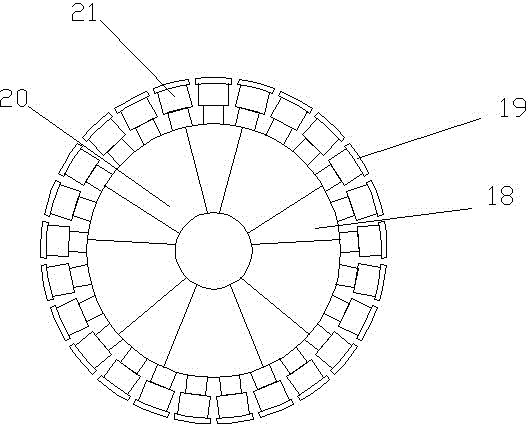
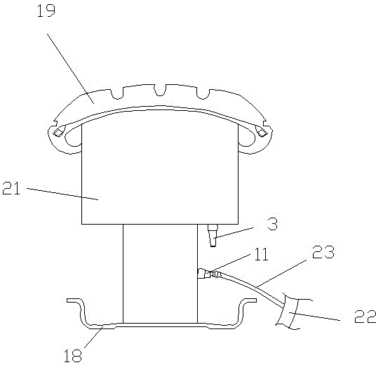
[0031] A kind of air-free wheel energy conversion system described in this embodiment 1, such as figure 1 , figure 2 As shown, it includes the wheel used in conjunction with the main frame of the car. The wheel is composed of a rim 18 mounted and connected to the axle, and spokes 20 provided on the rim. The annular surface of the rim facing the ground is provided with a reciprocating compression power device. The compression power device is a compressed air pump 21, and a plurality of compressed air pumps are arranged in a circular distribution along the annular surface of the rim, and each compressed air pump is independently provided with a tire rubber 19 on the end surface in contact with the bottom surface; each compressed air pump is provided with There is a return spring capable of resetting; each compressed air pump is connected to a generator located on the wheel rim or the main frame of the car, and the compressed air generated by the compressed air pump is used to g...

Embodiment 2

[0039] This embodiment 2 is improved on the basis of embodiment 1, and the specific difference of this embodiment 2 is:

[0040] The generator is directly installed and hidden in the main frame of the automobile. The generator can also be hidden in the main frame of the car and integrated with the main frame of the car to solve the installation position and complexity of the wheels.

Embodiment 3

[0042] This embodiment 3 is also improved on the basis of embodiment 1, and the specific difference of this embodiment 3 is:

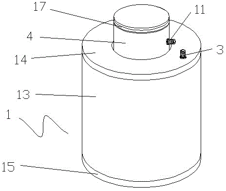
[0043] The generator is a screw expansion generator. The screw expansion generator can also be used for power generation. The working principle of the screw expansion generator can be roughly divided into:

[0044] 1. Air intake process: After the compressed air enters the inter-tooth volume of the rotor through the air inlet of the screw expansion generator, it will drive the rotor to rotate and make the inter-tooth volume continuously expand. When the inter-tooth volume is completely equal to the progress of the screw expansion generator When the air port is disengaged, the air intake process ends;

[0045] 2. Expansion process: As the volume between the teeth continues to increase, the volume expansion temperature of the compressed gas decreases, and at the same time, the power is output to the extended shaft of the rotor;

[0046] 3. Exhaust proc...


PUM


Abstract

The invention discloses an inflation-free-wheel energy conversion system comprising wheels. Each wheel comprises a rim and spokes. A plurality of air compressor pumps or reciprocating screw compressors are arranged along the annular surface, facing the ground, of each rim in an annular distribution mode. Tire rubber is independently arranged on the end face, contacting with the ground, of each air compressor pump or reciprocating screw compressor. Each air compressor pump or reciprocating screw compressor is provided with a reset spring and is connected with a generator arranged on the corresponding rim or a vehicle frame, and power generated by the air compressor pumps or the reciprocating screw compressors is utilized for electricity generation of the generators. During driving of a vehicle, rotation force or compressed air is generated when the ground applies acting force to the reciprocating screw compressors or the air compressor pumps, so that the rotation force or the compressed air generated continuously can be transmitted or delivered to the generators to generate electricity.

Description

technical field [0001] The present invention relates to the technical field of generating reciprocating compression power for power generation by using automobile driving, and in particular to a reciprocating compression power device which is installed on the rim and contacts the ground to generate power for power generation by utilizing the gravity of the automobile itself and driving power. power generation system. Background technique [0002] Tires are one of the important parts of the car. They are in direct contact with the road surface, and work together with the car suspension to ease the impact of the car while driving, ensuring that the car has good seating comfort and smooth driving; ensuring that the wheels and the road are in good condition The adhesion of the tire improves the traction, braking and passability of the car; bearing the weight of the car, the important role played by the tire on the car has attracted more and more attention. [0003] But the func...

Claims


Application Information

Patent Timeline
Patent Type & Authority Applications(China)
IPC IPC(8): B60K25/08H02K7/18
Inventor 冯柯霖
Owner 冯柯霖
Why Eureka
Try Eureka