Wing rudder driving device of flap type rudder

A technology of driving device and flap rudder, which is applied in directions such as rudder steering and steering, and can solve the problems of inconvenient installation of rudder bushings on the wing rudder, reducing the mechanical strength of the wing rudder, increasing the wing rudder, etc.

Inactive Publication Date: 2014-05-28
JIANGSU HUAYANG HEAVY IND +1
View PDF8 Cites 2 Cited by
  • Summary
  • Abstract
  • Description
  • Claims
  • Application Information

AI Technical Summary

Problems solved by technology

In the current flap rudder, the rudder cover and the wing rudder are mostly connected together by a key connection. Although the key connection can connect the rudder cover and the wing rudder together and transmit torque, the disadvantage is that 1. It is inconvenient to install the rudder casing to protect the wing rudder on the outside of the wing rudder, so that the wing rudder can be protected from seawater corrosion; 2. The requirements for gold processing of the rudder cover and the multiple keyways on the wing rudder are compared High, the position and size must be the same, otherwise a slight deviation will cause unbalanced force between the keys, resulting in easy wear and deformation of the keyway with large force, affecting the rudder turning effect of the flap rudder; 3. On the wing rudder Processing the keyway on the surface of the rod will inevitably reduce the mechanical strength of the wing rudder, or increase the true diameter of the wing rudder under the premise of keeping the mechanical strength of the wing rudder basically unchanged, thereby increasing the cost of the flap rudder
At present, there is no key connection between the rudder stock and the wing rudder, which is convenient for installing the rudder sleeve outside the wing rudder, and the flap rudder that protects the wing rudder from seawater corrosion is still rare, and has not been published in the data and media. found in the report

Method used


Image

  • Wing rudder driving device of flap type rudder

Examples


Embodiment Construction

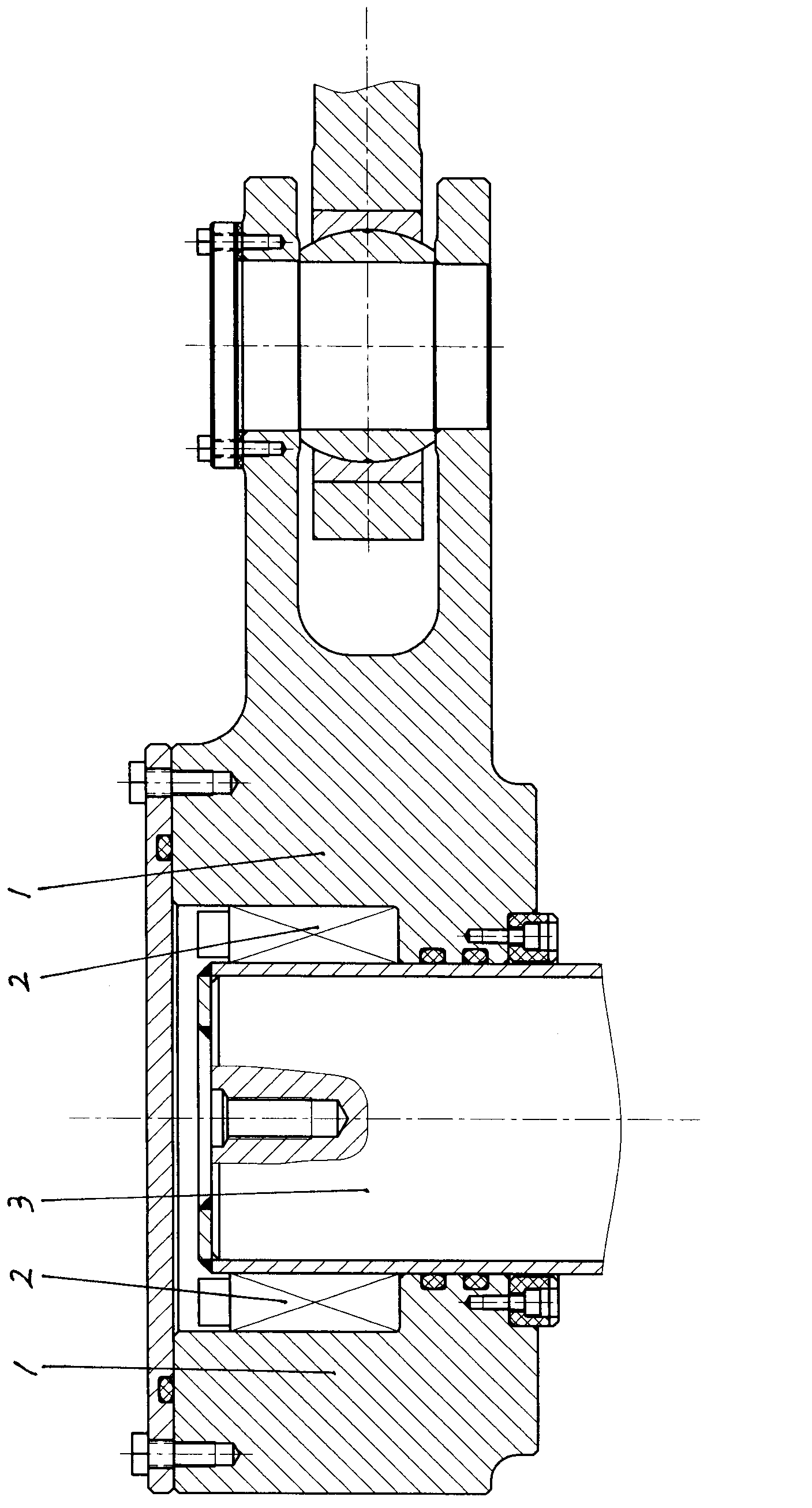
[0008] figure 1 Among them, the flap rudder wing rudder driving device is composed of wing rudder blades (not shown in the figure of wing rudder blades), wing rudder stock 3 and rudder stock cover 1, and the lower part of wing rudder stock 3 is fixedly installed on the top of wing rudder blades. The top of the wing rudder stock 3 is covered with a rudder stock cover 1, and an expansion joint sleeve 2 is installed between the wing rudder stock 3 and the rudder stock cover 1, and the wing rudder stock 3 and the rudder stock cover 1 are fixed by the expansion joint sleeve 2 Connected together, compared with the key connection, this connection method does not need to make grooves on the surface of the wing rudder stock 3 and the rudder stock 1, which reduces the metal processing accuracy and processing cost of the flap rudder, and does not affect the wing rudder stock. To improve the mechanical strength, a rudder cover can also be installed on the wing rudder to prevent seawater f...


PUM


Abstract

The invention relates to ship equipment, in particular to an advanced a flap type rudder of a ship. The wing rudder driving device of the flap type rudder comprises a wing rudder blade, a wing rudder rod and a rudder rod sleeve, wherein the lower portion of the wing rudder rod is fixedly connected onto the top of the wing rudder blade, the rudder rod sleeve sleeves the top of the wing rudder rod, and an expansion connection sleeve is mounted between the wing rudder rod and the rudder rod sleeve. Since a rudder sleeve tube can be mounted outside the wing rudder rod, the wing rudder rod is protected from being corroded by sea water, processing precision and cost for the flap type rudder can be reduced, and mechanical strength of the wind rudder rod and a rudder shifting effect of the flap type wing rudder cannot be affected.

Description

Technical field: [0001] The invention relates to ship equipment, in particular to the improvement of ship flap rudders. Background technique: [0002] Flap rudders are more and more used in ships because of their good rudder steering effect and simple structure. The current flap rudder drive device consists of wing rudder blades, wing rudder rods fixed on the wing rudder blades And the rudder stock cover fixed on the end of the wing rudder stock. The rudder stock cover and the rudder connecting rod are rotatably connected together, and the rudder stock is wrapped around the wing under the push (or pull) of the rudder connecting rod. The axis of the rudder stock rotates, thereby driving the wing rudder stock and the wing rudder blades to rotate. In the current flap rudder, the rudder cover and the wing rudder are mostly connected together by a key connection. Although the key connection can connect the rudder cover and the wing rudder together and transmit torque, the disadv...

Claims


Application Information

Patent Timeline
Patent Type & Authority Applications(China)
IPC IPC(8): B63H25/10
Inventor 丁晓阳陈宁丁郁华何志忠徐志明朱洁刘小琴王进储慧琳金雪磊马从龙王玲
Owner JIANGSU HUAYANG HEAVY IND
Why Eureka
Try Eureka