Back-carried type wire barrow

A pay-off car and knapsack technology, applied in the field of pay-off car, can solve the problems of being unsuitable for long-term use and heavy carrying, and achieve the effects of light weight, reduced carrying weight, and reasonable design.

Inactive Publication Date: 2014-05-28
XIAN KING TRUCK ELECTRON
View PDF0 Cites 5 Cited by
  • Summary
  • Abstract
  • Description
  • Claims
  • Application Information

AI Technical Summary

Problems solved by technology

[0003] The purpose of the present invention is to overcome the deficiencies in the above-mentioned prior art, and provide a knapsack pay-off vehicle, which has a simple structure, reasonable design, light weight, and good use effect, and can effectively solve the problem of the existing knapsack-type pay-off vehicle with a heavy load, It is not suitable for the problem of being used for a long time, and at the same time, the manufacture is simple and the manufacturing cost is low

Method used


Image

  • Back-carried type wire barrow
  • Back-carried type wire barrow
  • Back-carried type wire barrow

Examples


Embodiment Construction

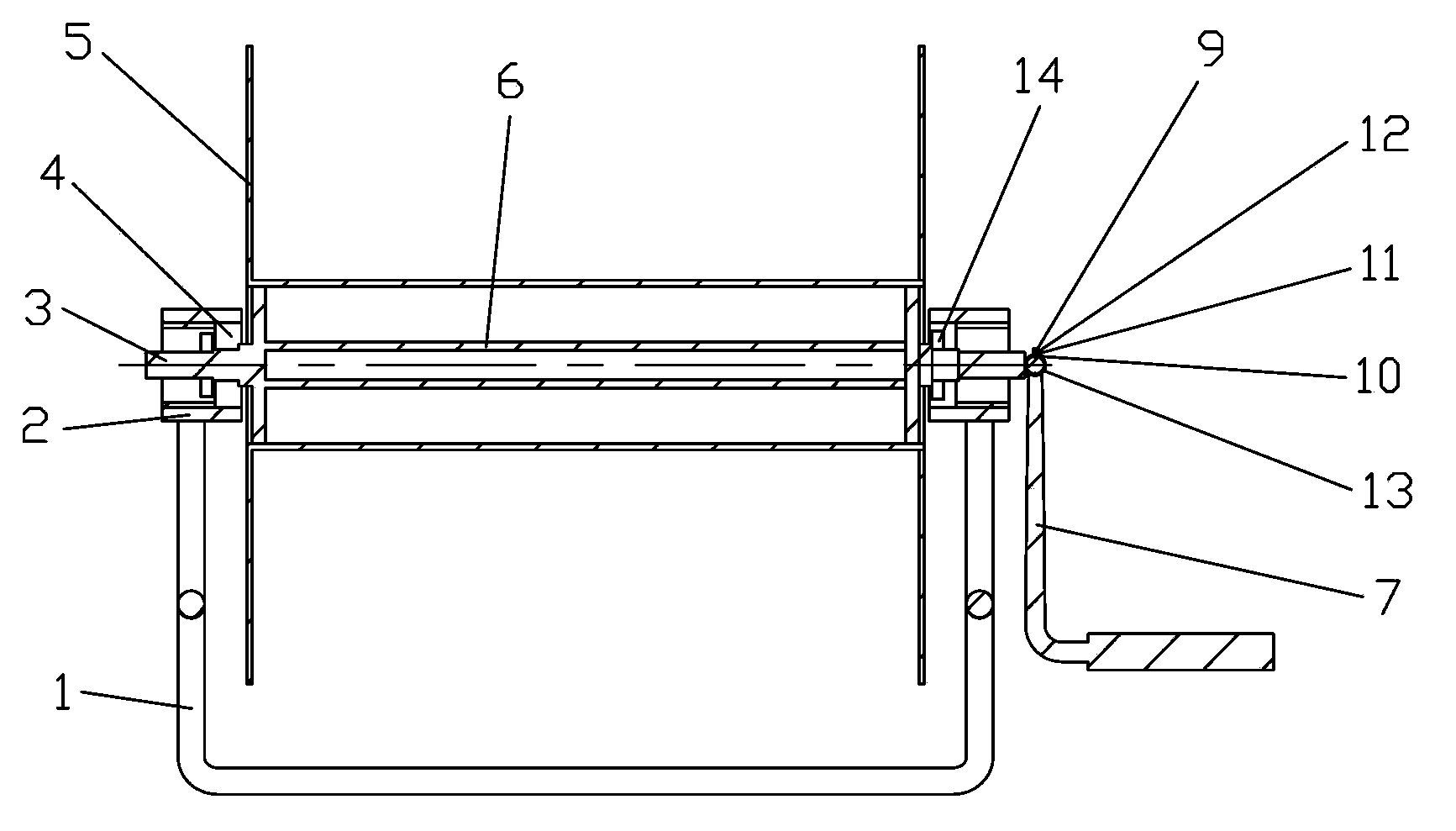
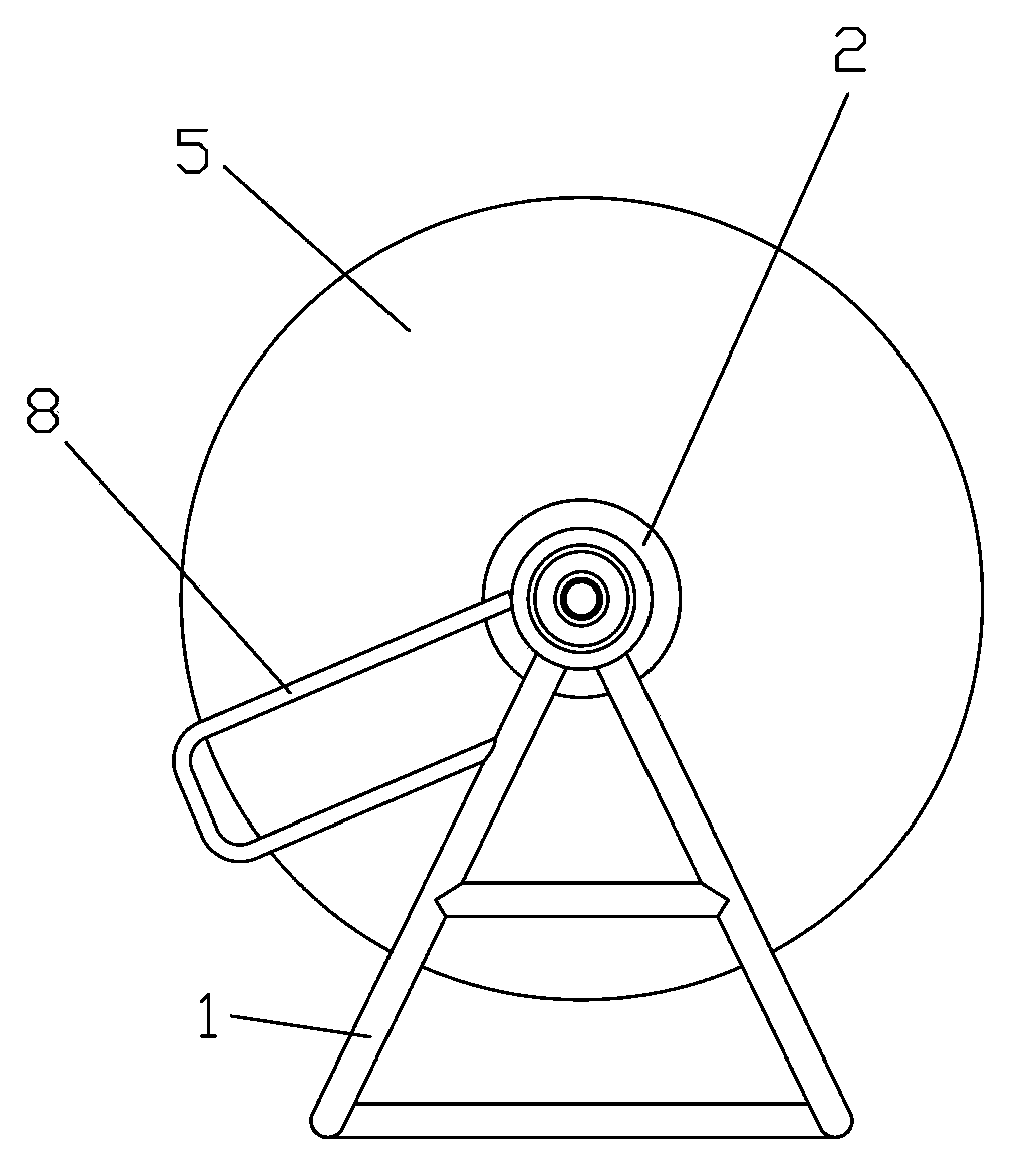
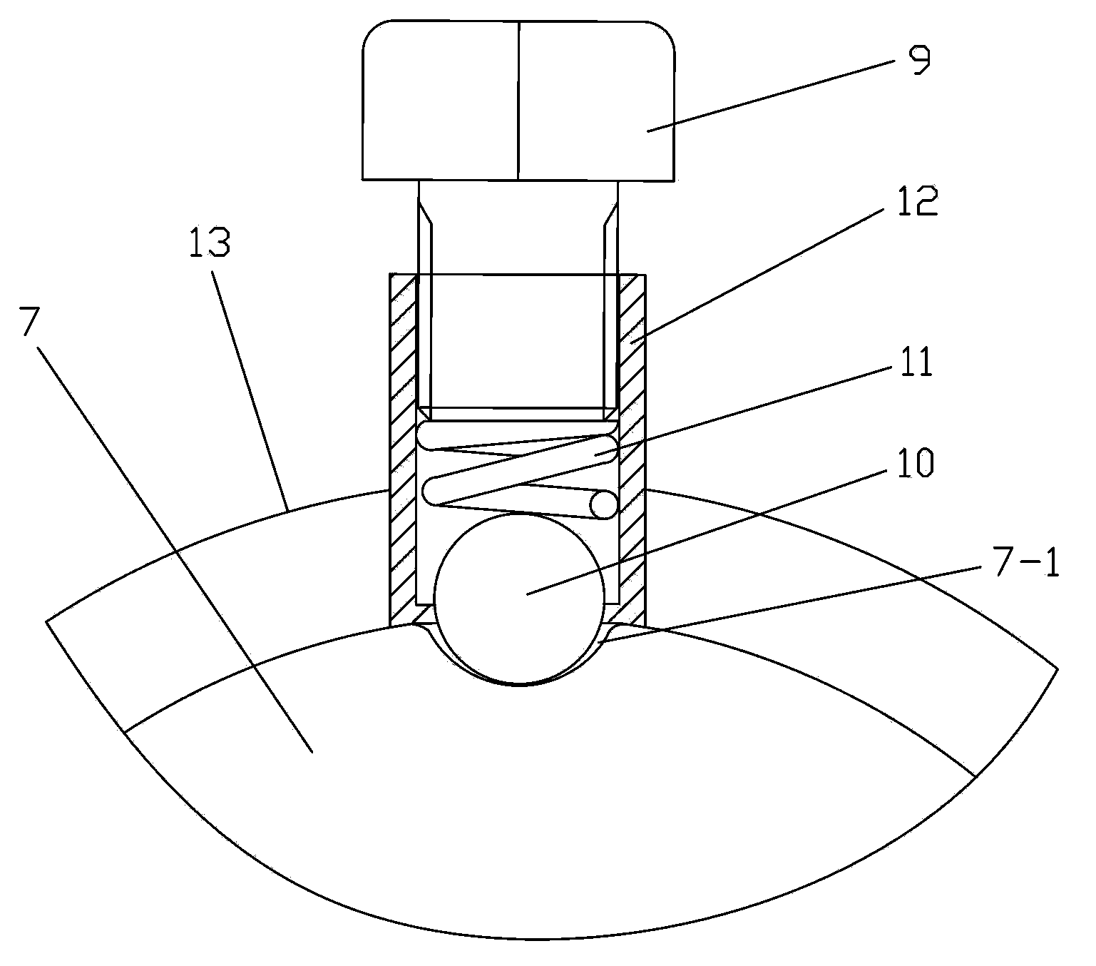
[0022] Such as figure 1 , figure 2 with Figure 4 As shown, the present invention includes a bracket 1, a bearing seat 2, a roller 3, a bearing 4, a winding roller 5, a connecting shaft 6 and a strap hanging ring 8, and is used to drive the roller 3 and the connecting shaft 6 to rotate together to realize the wire release With the handle rotation mechanism for taking up the wire, the support 1 is a triangular steel bar support, the number of the bearing seats 2 is two and the two bearing seats 2 are installed on the upper two ends of the support 1 respectively, and the number of the rollers 3 Two, the number of the bearing 4 is two, the roller 3 is installed on the bearing seat 2 through the bearing 4 and the end is locked by the nut 14, the connecting shaft 6 is a hollow tube, and the connecting shaft 6 The two ends of the two rollers 3 are welded respectively to form an integral rotating shaft. The winding roller 5 is a hollow plastic winding roller with a large plate at ...


PUM


Abstract

The invention discloses a back-carried type wire barrow which comprises a triangular reinforced steel bar support, two bearing blocks, two rolling shafts, two bearings, a wire winding roll, a connecting shaft, two strap hanging rings and a handle rotating mechanism. The two bearing blocks are respectively mounted at two ends of the upper portion of the support. The rolling shafts are mounted on the bearing blocks through the bearings and the ends of the rolling shafts are locked through nuts. The connecting shaft is a hollow tube. Two ends of the connecting shaft are respectively welded with the two rolling shafts to form an integral rotary shaft. The wire winding roll is a hollow plastic wire winding roll with large plates at two ends. The wire winding roll is fixedly mounted on the integral rotary shaft and rotates along with the same. The two strap hanging rings are respectively connected to two ends of the support. The back-carried type wire barrow is lightweight, good in application effect, simple to manufacture and low in manufacturing cost, and the problems that the existing back-carried type wire barrows are heavy to carry and not suitable for long-term back-carrying use.

Description

technical field [0001] The invention relates to a pay-off vehicle, in particular to a backpack type pay-off vehicle. Background technique [0002] The knapsack pay-off car is used to coil a certain length of soft cables such as telephone wires on the winding roller, and then the pay-off personnel put the pay-off car behind their backs to unfold the cables. line tool. The knapsack pay-off car is often used for the pay-off and take-up work of instruments used in the field. With the development of science and technology, there are more and more instruments such as field detection, and their scope of use is also wider and wider. The backpack-type pay-off vehicles seen in the market, including military pay-off vehicles, generally have the problem of being heavy and not suitable for carrying for a long time. Contents of the invention [0003] The purpose of the present invention is to overcome the deficiencies in the above-mentioned prior art, and provide a knapsack pay-off v...

Claims


Application Information

Patent Timeline
Patent Type & Authority Applications(China)
IPC IPC(8): B65H75/40B65H75/44
Inventor 赵明利
Owner XIAN KING TRUCK ELECTRON
Why Eureka
Try Eureka