Synchronous construction method for constructing suspended rail beam and roof

A technology of simultaneous construction and construction method, applied in the direction of house structure support, house structure support, construction, etc., can solve the problems of increasing the cost of scaffolding, reducing the density of scaffolding, long density of scaffolding, etc., to reduce the cost of erection and material turnover. Costs, reduction of secondary scaffolding, good social and economic benefits

Active Publication Date: 2014-05-28
CHINA CHEM ENG SECOND CONSTR
View PDF7 Cites 1 Cited by
  • Summary
  • Abstract
  • Description
  • Claims
  • Application Information

AI Technical Summary

Problems solved by technology

[0006] (2) Because the scaffolding for the installation of the suspension rail beam must be erected before the suspension rail beam can be hoisted, the suspension rail beam penetrates from the outside into the room, and the installation is difficult
[0007] (3) The scaffolding installed for the installation of suspension rail beams is not as stable as the scaffolding for roof construction
In order to save trouble, the operators spontaneously strive to reduce the density of scaffolding, which poses a greater safety risk
[0008] (4) Due to the long erection density of scaffolding, the risk of installing suspension beams on it is greater
[0009] (5) Since there is no hoisting point for the hoisting of the suspension rail beam, hoisting holes must be opened on the roof, and the roof structure needs to be partially destroyed. The waterproof treatment is difficult and water leakage is very easy to occur
[0010] (6) The lifting holes of the suspension beam lifting points are easily blocked during the civil construction process, and the processing efficiency is low
[0011] (7) The construction period is long, and it can only be installed after the main body of the civil works is installed
[0012] (8) High cost: the second erection of scaffolding will increase the cost of scaffolding erection, the operation is difficult, and labor costs will be increased

Method used


Image

  • Synchronous construction method for constructing suspended rail beam and roof

Examples


Embodiment Construction

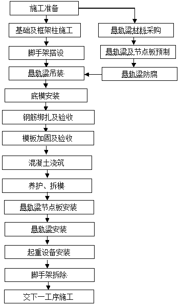
[0033] figure 1 As shown, the process flow of the present invention includes foundation and frame column construction, scaffold erection, roof construction, suspension rail beam hoisting, base form installation, steel bar binding, formwork support and reinforcement, concrete pouring, maintenance and formwork removal, suspension rail Beam gusset plate installation, suspension rail beam installation, crane equipment installation, scaffolding removal, characterized in that after the foundation and frame columns are constructed, scaffolding is erected under the projected area of ​​the roof, and then the suspension rail beams are hoisted to the position below the installation, and then the roof is installed And the roof beam bottom formwork, binding steel bars, side formwork reinforcement, concrete pouring, when the condition of removing the formwork and scaffolding is achieved after curing, the formwork is removed, and the suspension rail beam gusset plate is installed, the suspens...


PUM

PropertyMeasurementUnit
Widthaaaaaaaaaa
Thicknessaaaaaaaaaa

Abstract

The invention relates to a synchronous construction method for constructing a suspended rail beam and a roof, and belongs to the field of an industrial building. The method comprises the erection of a scaffold, the location of the suspended rail beam, and the construction of the roof. The method is characterized in that when the roof and a roof beam are constructed, the suspended rail beam is placed and located on the erected scaffold, and the weight of the suspended rail beam is born by the scaffold. Before the roof beam and the roof are filled with concrete and are maintained, the suspended rail beam is mounted on the roof beam. The method adopts the scaffold which is used for erecting the roof in one time, the construction of the roof and the construction of the suspended rail beam are completed in one time, the repeated erection of the scaffold is reduced, the convenient location of the suspended rail beam is realized, the safe construction is ensured, the construction time is shortened, and the cost is reduced.

Description

technical field [0001] The invention belongs to the field of industrial construction, and is mainly applicable to the installation of roof suspension beams with an indoor height of more than 3m, especially the installation of single-layer suspension beams greater than 3m, such as underground circulating water station pump rooms, various pump stations, and large fan rooms. , Installation of lifting equipment for suspension rail beams with a storey height greater than 3m and a small amount of maintenance. Background technique [0002] Single-storey industrial plants with an indoor height of more than 3m and need to install suspension beams are very common in large industrial plants, such as underground pump stations, belt machine heads, large fan rooms, and dynamic equipment plants with not too much maintenance. [0003] Conventional construction techniques are adopted, and the construction procedures are factory building frame construction—full house scaffold erection—roof be...

Claims


Application Information

Patent Timeline
IPC IPC(8): E04G21/00E04G21/14E04G1/02
Inventor 薛慧峰陈银川代卫国李鑫
Owner CHINA CHEM ENG SECOND CONSTR
Why Eureka
Try Eureka